Jet pump

A jet pump, annular technology, applied in the direction of jet pump, pump, jet device, etc., can solve the problem of incompatibility, and achieve the effect of high suction rate, small weight and easy realization

Inactive Publication Date: 2012-10-03
韩铁夫
View PDF7 Cites 16 Cited by
  • Summary
  • Abstract
  • Description
  • Claims
  • Application Information

AI Technical Summary

Problems solved by technology

It is a jet pump composed of a circle of small single-tube ejectors connected in parallel and a central one-way ball valve. In fact, it is a first-stage p...

Method used


Image

  • Jet pump
  • Jet pump
  • Jet pump

Examples


Embodiment 1

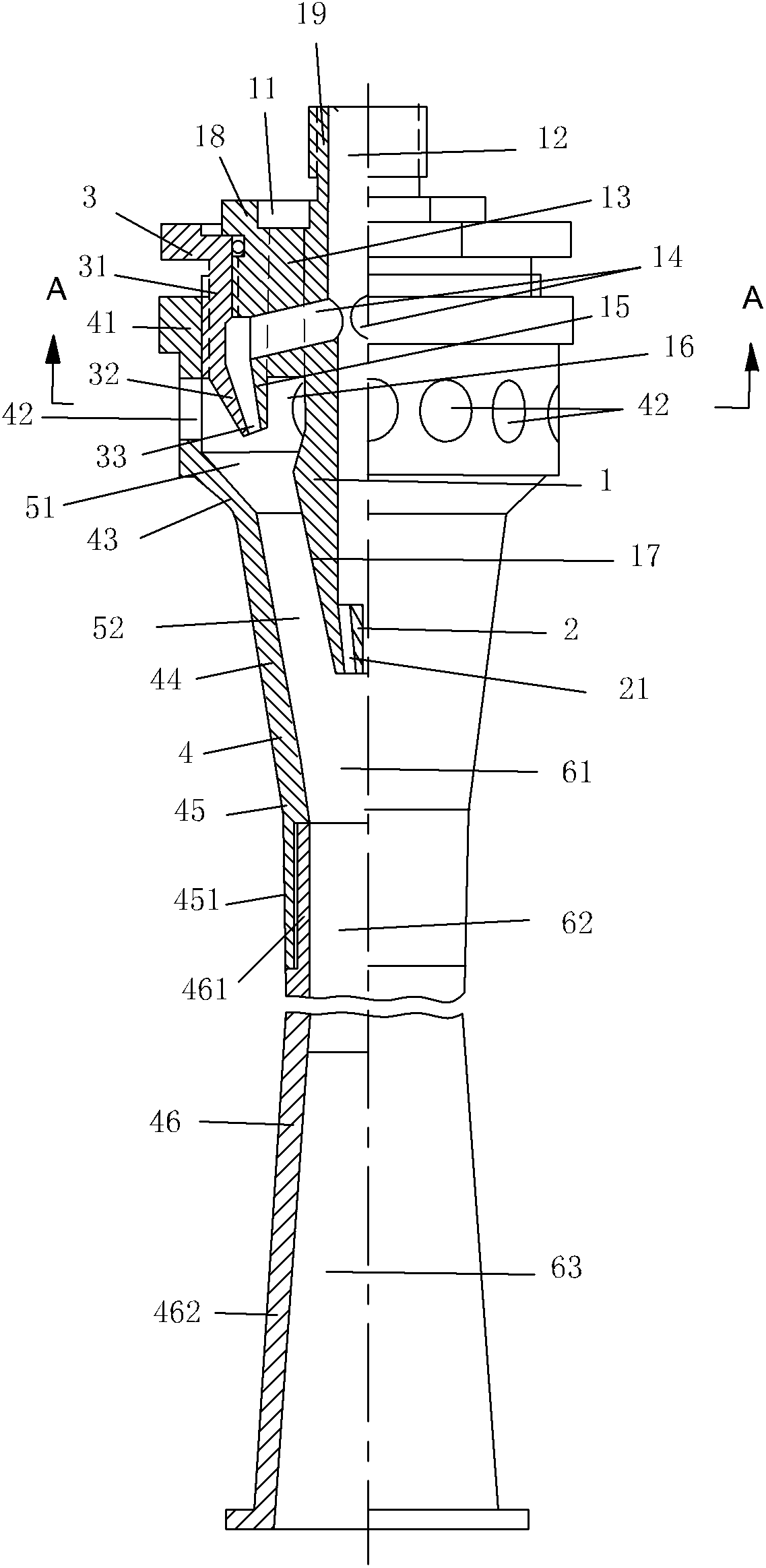
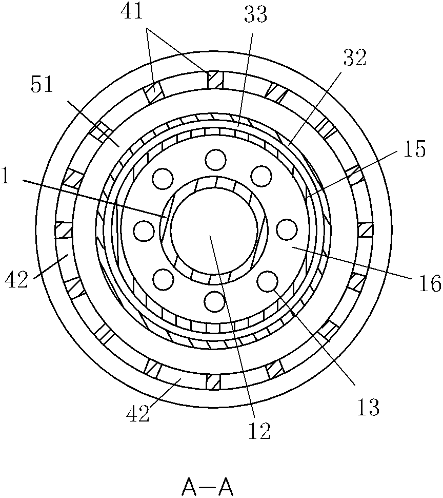
[0041] The structure of the first embodiment of jet pump of the present invention, as figure 1 shown. The jet pump consists of a central tube 1 , a central nozzle 2 , an intermediate sleeve 3 , an outer tube 4 and an outer tube extension 46 . figure 1 The upper part is the actual front, and the lower part is the actual rear.

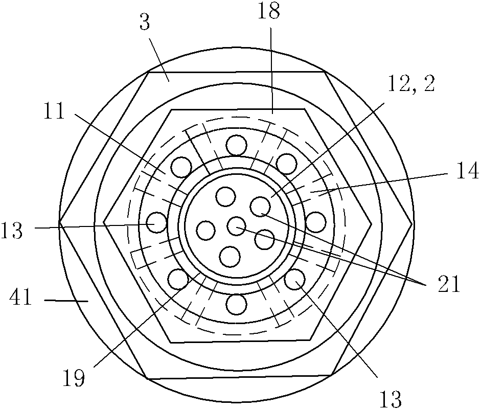
[0042] The front end of the central pipe 1 is a pipe joint 19 with the smallest diameter, and the front part is an outer flange 18 with the largest diameter. The rear portion 15 of the outer flange 18 shrinks backward gradually and digs a groove 16 inward, and the rear portion 17 of the central pipe 1 continues to shrink gradually. Please see figure 2 A groove 11 is formed around the pipe joint 19 on the front end surface of the outer flange 18, and a plurality of longitudinal through holes 13 are evenly distributed, and these longitudinal through holes 13 run through the front and rear end faces of the outer flange 18 to reach the front of the groov...

Embodiment 2

[0054] The structure of the second embodiment of jet pump of the present invention, as Figure 4 shown. The jet pump consists of a central tube 10 , a central nozzle 20 , a middle sleeve 30 , an outer tube front sleeve 340 , and an outer tube main part 40 . Figure 4 The upper part is the actual front, and the lower part is the actual rear.

[0055] The front end of the center pipe 10 is a pipe joint 190 with the largest diameter, and the front and middle parts are outer flanges 110 with a medium diameter. A hexagonal cap 180 protruding outward is provided between the outer flange 110 and the pipe joint 190 . The front part of the outer flange 110 is provided with external threads. The rear portion 170 of the base pipe 10 is the smallest diameter straight pipe section. The inner hole 120 of the central pipe 10 is a stepped straight circular hole with a large front and a small rear, and penetrates from the front end surface of the pipe joint 190 to the rear end surface of t...

Embodiment 3

[0069] The structure of the third embodiment of the jet pump of the present invention, as Figure 9 shown. Figure 9 The upper part is the actual front, and the lower part is the actual rear. In the jet pump: the central tube is divided into a central tube front section 100 and a central tube rear section 200; the structure of the middle sleeve 300 is the same as that of the middle sleeve 3 in the first embodiment; the outer tube main body 400 and the outer tube extension 4600 The composed outer tube is provided with a large-diameter pipe section 4200, a first constricted cone pipe section 4300, a front transition pipe section 4400, an intermediate tapered pipe section 4500, a rear transition pipe section 46100, and a second tapered pipe section 46200 along the central axis from front to back. The rear straight pipe section 46300; the central nozzle 700 can adopt the structure of the central nozzle 2 or the central nozzle 20 in the above two embodiments.

[0070] The front e...


PUM


Abstract

The invention discloses a jet pump and relates to mixed flow elements of fluid. An annular ejector of the jet pump is coaxially and serially arranged at the front end of a central ejector; the annular ejector comprises an annular nozzle, an annular mixing chamber and an annular mixing pipe; the central ejector comprises a central nozzle, a central mixing chamber and a central mixing pipe; a primary fluid inlet is laterally communicated with the annular nozzle and is directly communicated with the central nozzle at the tail end of a central pipe; a secondary fluid inlet is communicated with a side wall of the annular mixing chamber; one part of primary fluid is ejected to be introduced into secondary fluid of the annular mixing chamber through the annular nozzle and is mixed in the annular mixing pipe, and annular mixed flow is output; and the other part of primary fluid is jetted to an outlet of the central mixing pipe through the central nozzle and is ejected to enter the annular mixed flow in the central mixing chamber, and the primary fluid and the annular mixed flow are subjected to secondary mixing in the central mixing pipe and are output, so that suction of high-pressure primary fluid and mixed flow delivery of low-pressure secondary fluid are finished. The jet pump which is formed by sleeving and connecting two ejectors in series is small in axial size and high in ejection rate and output pressure.

Description

technical field [0001] The invention relates to a fluid mixing element. Background technique [0002] The jet pump is a mixed-flow element that uses a high-pressure primary fluid to inject a low-pressure or no-pressure secondary fluid, and outputs a medium-pressure mixed fluid. The most typical structure of the existing ejectors is the Venturi ejector. The body of the Venturi ejector is a circular tube with a reaming cavity mixing chamber at the front end, and a secondary fluid inlet is set on the side of the mixing chamber. A nozzle connected to the main fluid inlet pipe is arranged in the chamber, and the outlet of the nozzle is directly connected to the small-diameter mixing output pipe connected to the outlet of the constricting cone of the mixing chamber. [0003] The Venturi ejector passes through the nozzle, so that the working fluid entrains the injected secondary fluid into the mixing chamber and enters the mixing output pipe. The two are mixed in the mixing tube ...

Claims


Application Information

Patent Timeline
IPC IPC(8): F04F5/00
CPCF04F5/04B05B7/045B05B1/3415F04F5/16B05B7/0491B05B7/0458F04F5/463
Inventor 韩铁夫
Owner 韩铁夫
Why Eureka
Try Eureka