Brake cylinder device and disk brake device

A technology of brake cylinder and cylinder main body, applied in the field of brake cylinder device and disc brake device

Active Publication Date: 2012-10-03
NABLESCO CORP
View PDF9 Cites 6 Cited by
  • Summary
  • Abstract
  • Description
  • Claims
  • Application Information

AI Technical Summary

Problems solved by technology

Therefore, it will be a factor that is limited when the diameter dimension of the rear side of the cylinder main body in which the piston is arranged can be reduced in size.

Method used


Image

  • Brake cylinder device and disk brake device
  • Brake cylinder device and disk brake device
  • Brake cylinder device and disk brake device

Examples


no. 1 Embodiment approach

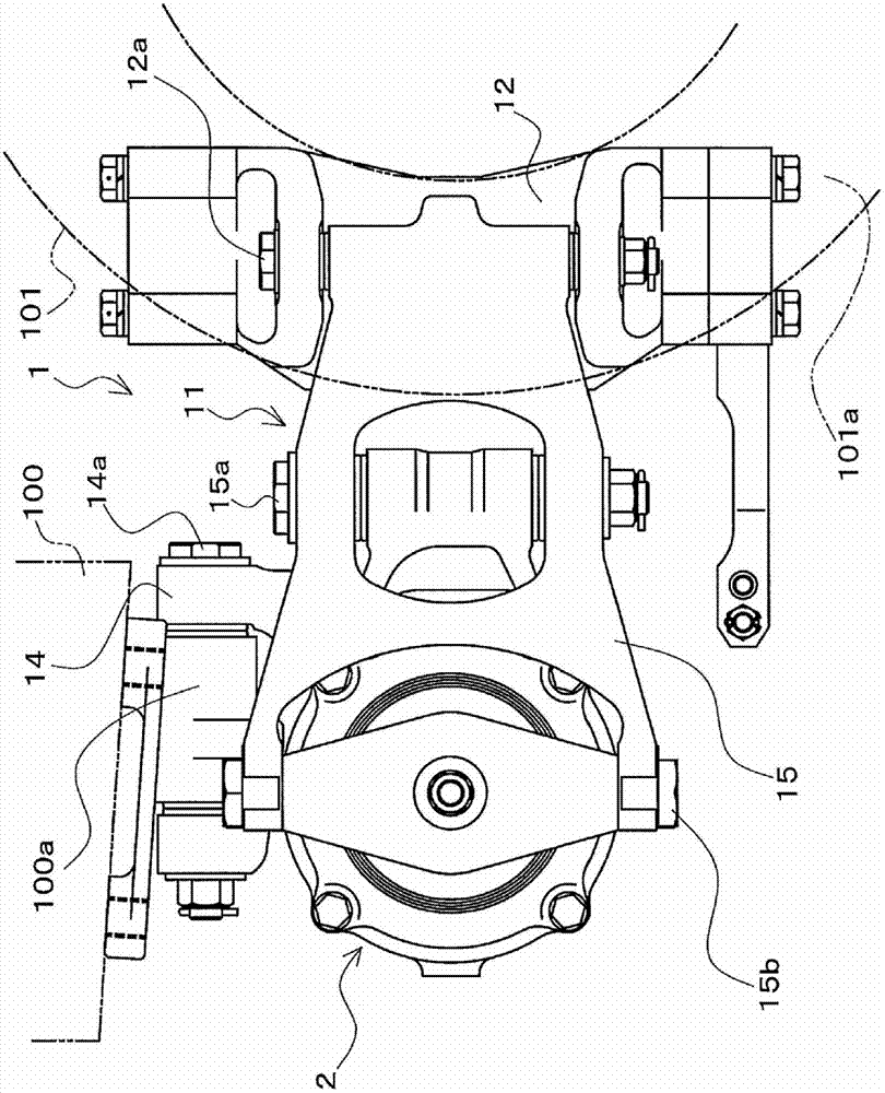
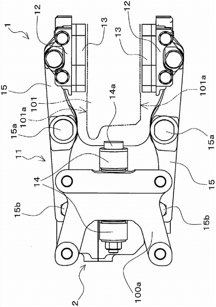
[0063] figure 1 It is a side view of the disc brake device 1 according to the embodiment of the present invention viewed from the axle direction. in addition, figure 2 is viewed from above figure 1 A plan view of the disc brake device 1 shown. figure 1 and figure 2 The shown disc brake device 1 includes: a brake cylinder device 2; a caliper main body 11 for equipping the brake cylinder device 2 and mounted on the vehicle body 100 in a manner capable of relative displacement in the axle direction. A vehicle main body 100; a pair of lining plates (12, 12), which are brake pad holding portions for respectively holding a pair of brake pads (13, 13) as brake pads.

[0064] A pair of brake pads ( 13 , 13 ) are attached to the caliper main body 11 via a backing plate 12 . In addition, the disc brake device 1 clamps the disc on the axle side that rotates with the rotation of the wheels (not shown) of the railway vehicle by a pair of brake pads ( 13 , 13 ) through the operation ...

no. 2 Embodiment approach

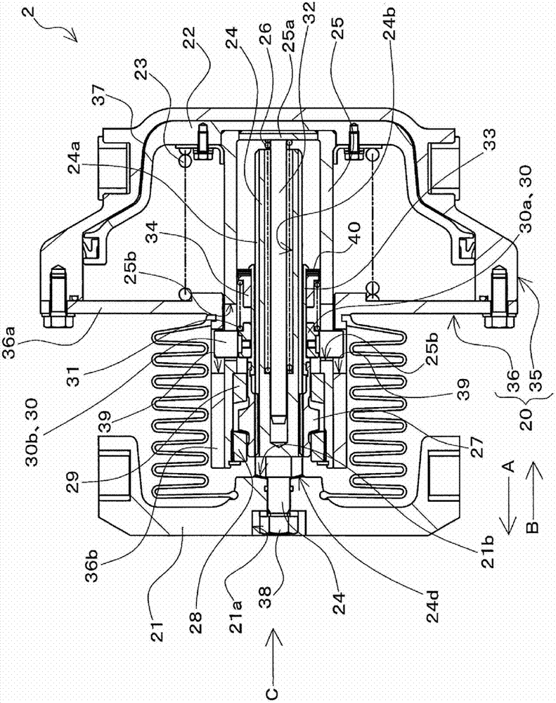
[0136] Next, a brake cylinder device 3 according to a second embodiment of the present invention will be described. Figure 21 It is a sectional view of the brake cylinder device 3 of the second embodiment. Figure 21 The shown brake cylinder device 3 is provided as a brake cylinder device equipped in the disc brake device 1 similarly to the brake cylinder device 2 of the first embodiment. In addition, in Figure 21 In FIG. 3 , the cross-section is not shown but the outer diameter is shown for some components of the brake cylinder device 3 .

[0137] The brake cylinder device 3 includes the cylinder main body 20, the brake output part 21, the piston 50, the piston spring 23, the threaded shaft 24, the guide pipe 25, the thrust spring 26, and the clutch nut similarly to the brake cylinder device 2 of the first embodiment. 27. Front clutch 28, rear clutch 29, stopper 30, adjustment spring 31, thrust spring guide 32, adjustment sleeve 33, spring stopper 34, nut member 38, beari...


PUM


Abstract

Provided is a brake cylinder device such that there exists a gap adjustment mechanism, that it is possible to prevent, at low cost, susceptibility to the influence of ambient environmental factors such as temperature and humidity, and that the radial dimensions of a cylinder body can be made compact. A threaded shaft (24) connected to a brake output section (21) is placed inside a guide tube (25) installed in a piston (22). A pressure spring (26) applies force to the threaded shaft (24) in the braking direction. A clutch nut (27) threadably engages with the tip portion of the threaded shaft (24). A front clutch (28) and a rear clutch (29) are disposed in such a way as to be capable of abutting the front side and the rear side, respectively, of the clutch nut (27). A stop (30) is disposed in such a way as to be capable of moving relative to the clutch nut (27) and the guide tube (25) along the axial direction of the threaded shaft (24), and the movable range is restricted with respect to the cylinder body (20). An adjustment spring (31) is provided in such a way that one end thereof abuts the stop (30), and that it is possible to apply force to the clutch nut (27) in the anti-braking direction.

Description

technical field [0001] The present invention relates to a brake cylinder device having a clearance adjustment mechanism for automatically adjusting the distance between a brake released state and a brake action position, and a disc brake device having the brake cylinder device. gap. Background technique [0002] A brake cylinder device disclosed in Patent Document 1 is known, which has a gap adjustment mechanism for automatically adjusting the brake cylinder from the state where the brake is released to the brake operating position (position where braking force can be generated). gap. In the brake cylinder device disclosed in Patent Document 1, a jack and a guide member capable of moving together with the jack are provided, and the jack has a concave-convex surface formed on its outer surface. Moreover, an O-ring engaged with the uneven surface is arranged in the space between the guide member and the ejector rod. When a force greater than a predetermined value is applied ...

Claims


Application Information

Patent Timeline
Patent Type & Authority Applications(China)
IPC IPC(8): F16D65/18F16D65/56B61H15/00F16D55/224F16D121/04
CPCF16D55/2245F16D2121/02B61H5/00B61H15/0057F16D65/28F16D65/56B61H15/00F16D55/224F16D65/18
Inventor 大野智也小泽洋一郎中村丈一
Owner NABLESCO CORP
Why Eureka
Try Eureka