Vehicle speed sensor mounting structure

A vehicle speed sensor and structure technology, which is applied in the field of vehicle speed sensor installation and structure, can solve the problems of vehicle speed sensor disassembly or maintenance difficulties, and achieve the effects of improving the readiness, reducing the quantity, and improving the readiness

Inactive Publication Date: 2012-11-21
HONDA MOTOR CO LTD
View PDF5 Cites 7 Cited by
  • Summary
  • Abstract
  • Description
  • Claims
  • Application Information

AI Technical Summary

Problems solved by technology

[0007] However, since the vehicle frame, the engine hanger, the swing arm pivot, and the like are collectively arranged close to the crankcase on the rear surface portion of the crankcase, in the vehicle speed sensor mounting structure described in Patent Document 1, care must be taken when assembling the engine. Sometimes the frame and the vehicle speed sensor do not interfere, and once the vehicle is assembled, it may become difficult to disassemble or maintain the vehicle speed sensor

Method used


Image

  • Vehicle speed sensor mounting structure
  • Vehicle speed sensor mounting structure
  • Vehicle speed sensor mounting structure

Examples


Embodiment Construction

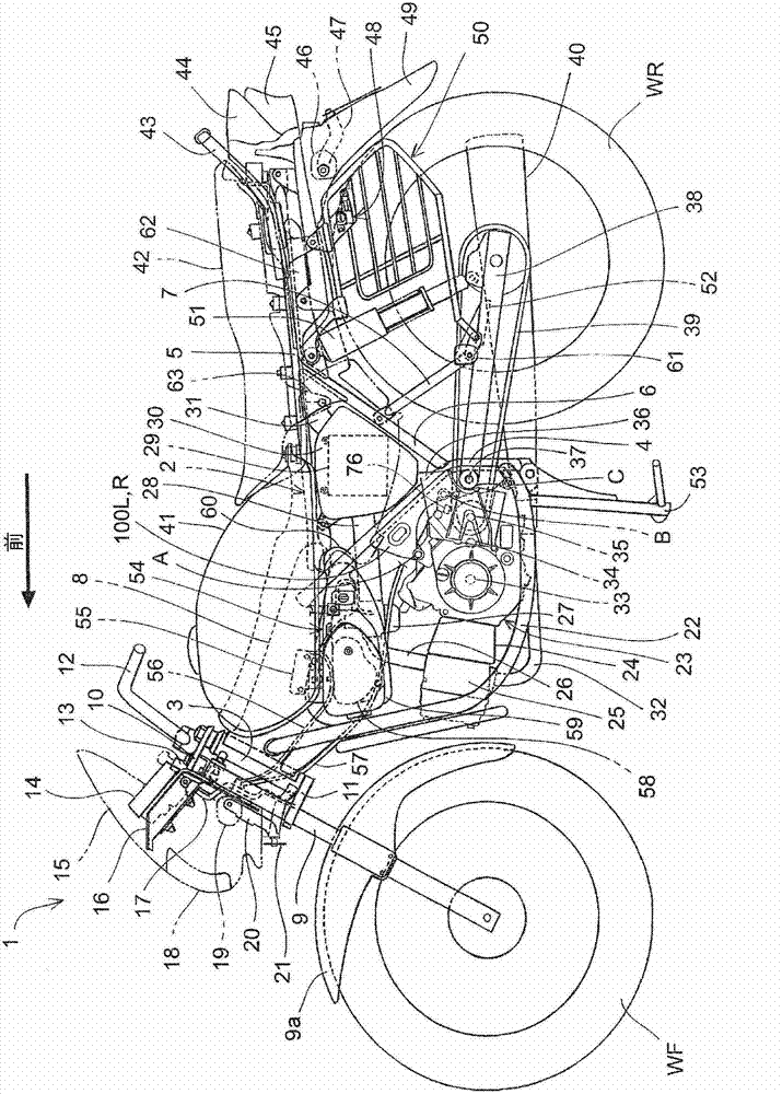
[0042] Hereinafter, preferred embodiments of the present invention will be described in detail with reference to the drawings. figure 1 It is a side view of the motorcycle 1 to which the vehicle speed sensor mounting structure of the present invention is applied. The frame 2 of the motorcycle 1 includes: a head pipe 3 at the front end of the vehicle body; a main frame 8 extending rearward from the head pipe 3; a pair of left and right seat rails connected to the rear end of the main frame 8 and extending rearward. 5; a pair of left and right down frames 22 connected to the front end of the main frame 8 and extending downward; a pair of left and right central frames extending downward from the rear of the main frame 8 and connected to the rear end of the down frame 22 4; and a pair of left and right subframes 6 connecting the seat rail 5 and the center frame 4 . A center ladder 53 is rotatably attached to the lower end of the center frame 4 .

[0043] A front fork 9 is attach...


PUM


Abstract

Provided is a vehicle speed sensor mounting structure for mounting a vehicle speed sensor by means of a simple configuration to an area in which maintenance is easily performed while protecting the vehicle speed sensor. A vehicle speed sensor (77) is secured to a crank case (64) by fastening the vehicle speed sensor (77) together with a protector (83), which covers the upper section of the vehicle speed sensor (77), by means of a fastening member while the axis (O) of the roughly cylindrical main body (78) of the vehicle speed sensor (77) is tilted a prescribed angle ([theta]) towards the rear side of the vehicle body when viewing the vehicle from the side and on a position which is on the upper side of a sub-shaft (35) and the rear side of a shift drum (150) with respect to the vehicle body. By inserting the main body (78) of the vehicle speed sensor (77) into a through hole (73) formed on the crank case (64), the detection unit (78a) of the vehicle speed sensor (77) faces the tip of the tooth of a second-speed driven gear (G2). The through hole (73) through which the main body (78) is inserted and a fastening hole (74) through which the fastening member (81) is inserted are disposed on a fastening base (72) formed on the crank case (64). The fastening hole (74) is disposed on the outside in the vehicle width direction of the through hole (73).

Description

technical field [0001] The present invention relates to a vehicle speed sensor installation structure, in particular to a vehicle speed sensor installation structure for installing a vehicle speed sensor on a crankcase of an engine. Background technique [0002] Conventionally, in order to detect a vehicle speed based on a rotational speed of a counter shaft of a transmission, a structure in which a vehicle speed sensor is attached to a crankcase of an engine is known. [0003] Patent Document 1 discloses a vehicle speed sensor installation structure in which the detection portion of the vehicle speed sensor is directed toward the front of the vehicle body, the detection portion is opposed to the tooth top of the gear that rotates integrally with the countershaft of the transmission, and is located on the wall surface of the crankcase on the rear side of the vehicle body. Install the vehicle speed sensor. [0004] prior art literature [0005] patent documents [0006] Pa...

Claims


Application Information

Patent Timeline
Patent Type & Authority Applications(China)
IPC IPC(8): F02D35/00B62J99/00B62M7/02
CPCB62J99/00
Inventor 林宽渡边觉
Owner HONDA MOTOR CO LTD
Why Eureka
Try Eureka