Adjustable center propeller bearing device

A technology for bearing devices and propellers, applied in the direction of bearing components, shafts and bearings, sliding contact bearings, etc., can solve the problems of reducing the service life of bearings, dry friction and crawling, self-excited vibration of bearings, etc., and achieve strong wear resistance and corrosion resistance , prolong the service life and improve the performance

Active Publication Date: 2015-11-18
CHINA SHIP DEV & DESIGN CENT
View PDF7 Cites 0 Cited by
  • Summary
  • Abstract
  • Description
  • Claims
  • Application Information

AI Technical Summary

Problems solved by technology

Due to the large mass of the propeller itself, and it is installed at the end of the tail shaft, the end of the tail shaft is cantilevered, which is prone to bending deformation, and the existing bearing is fixed, so it is easy to make the contact between the bearing and the tail shaft uneven along the axis direction, causing The local specific pressure is too large, forming the "edge load" phenomenon, causing excessive local wear of the bearing, thereby reducing the service life of the bearing; and the "edge load" phenomenon makes it impossible to form a good lubricating film between the shaft and the bearing, resulting in dry friction and crawling phenomenon , resulting in self-excited vibration of bearing friction, and then howling, especially when the frequency of friction vibration is consistent with the local frequency of the shafting or hull, it will cause resonance of the local structure of the shafting or hull, resulting in strong vibration and noise, affecting the ship's Acoustic hidden performance

Method used


Image

  • Adjustable center propeller bearing device
  • Adjustable center propeller bearing device
  • Adjustable center propeller bearing device

Examples


Embodiment Construction

[0017] Embodiments of the present invention will be further described in detail below in conjunction with the accompanying drawings.

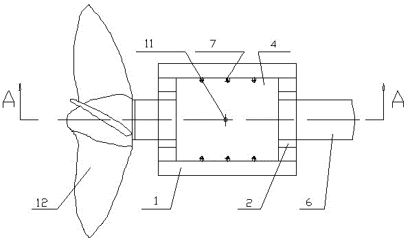
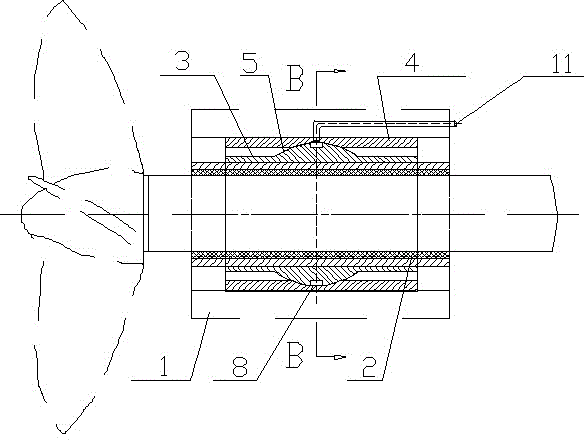
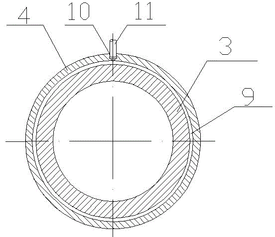
[0018] It includes a bearing seat 1 that is fixedly connected with the stern frame of the hull, and a self-aligning sleeve is installed on the inner cavity seat of the bearing seat. The outer sleeve 4 of the seat, the outer peripheral spherical surface of the inner sleeve is a convex spherical surface 5, and the ball seat of the outer sleeve is a concave ball seat. The diameter of the convex spherical surface of the inner sleeve is larger than the outer peripheral diameter of the inner sleeve, and the diameter of the convex spherical surface of the inner sleeve is smaller than the axial length of the inner sleeve. The inner sleeve is fitted in the inner hole of the outer sleeve, the diameter of the spherical surface of the concave ball seat of the outer sleeve is the same as the diameter of the convex spherical surface of the inner sleeve, the ...


PUM


Abstract

The invention relates to an aligning propeller bearing device applied to the tail end of a ship. The aligning propeller bearing device comprises a bearing seat and a propeller bearing arranged in an inner cavity of the bearing seat, and is characterized in that an aligning support sleeve is arranged between an inner cavity hole seat of the bearing seat and the propeller bearing; the aligning support sleeve comprises an inner support sleeve of which the periphery is provided with a spherical surface, and an outer support sleeve of which the inner hole is provided with a corresponding sphere seat; the inner support sleeve is sleeved in the inner hole of the outer support sleeve; and the peripheral spherical surface of the inner support sleeve is matched with the sphere seat of the outer support sleeve. Due to the adoption of the aligning propeller bearing device, the propeller bearing can be adjusted finely by swinging in any direction, the function of automatically aligning along with a shaft condition is realized, the propeller bearing is in uniform contact with a tail shaft along the axis direction, the service performance of the propeller bearing is improved, the abrasion can be reduced, the service life of the bearing is prolonged, the generation of noise is reduced and avoided, and convenience is brought to the installation of the tail shaft and the propeller bearing. Lubricating grease for a ship is injected through a lubricating oil pipeline, so that lubrication and rust prevention of the aligning support sleeve are realized, and the aligning function of the aligning support sleeve is ensured.

Description

technical field [0001] The invention relates to an adjustable propeller bearing device used at the tail end of a ship. Background technique [0002] The propeller is an important equipment of the ship propulsion system, and the propeller bearing device is used to support part of the weight of the propeller and shafting. The existing ship propeller bearing is composed of a shaft sleeve and a rubber strip installed in the inner hole of the shaft sleeve, and the bearing is fixedly installed in the bearing seat and configured with the tail shaft. Due to the large mass of the propeller itself, and it is installed at the end of the tail shaft, the end of the tail shaft is cantilevered, which is prone to bending deformation, and the existing bearing is fixed, so it is easy to make the contact between the bearing and the tail shaft uneven along the axis direction, causing The local specific pressure is too large, forming the "edge load" phenomenon, causing excessive local wear of t...

Claims


Application Information

Patent Timeline
Patent Type & Authority Patents(China)
IPC IPC(8): F16C23/04F16C33/10F16C33/12
Inventor 李全超刘义军周睿刘瑞海郭全丽李栋梁
Owner CHINA SHIP DEV & DESIGN CENT
Why Eureka
Try Eureka