A shaft pinch clamp centering device

A technology of shaft parts and fixing rings, which is applied in the field of shaft centering and fixing devices, can solve the problems of inability to achieve centering and centerline offset, and achieve the effects of convenient centering and clamping, reliable operation and simple structure.

Active Publication Date: 2016-05-25
TIANRUN IND TECH CO LTD
View PDF6 Cites 0 Cited by
  • Summary
  • Abstract
  • Description
  • Claims
  • Application Information

AI Technical Summary

Problems solved by technology

Although the various clamping devices currently in use can clamp the parts, they cannot be centered, and the center line often deviates.

Method used


Image

  • A shaft pinch clamp centering device
  • A shaft pinch clamp centering device

Examples


Embodiment Construction

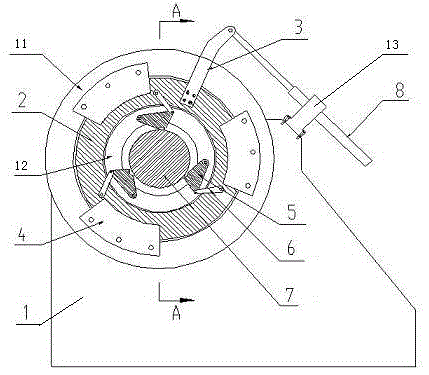
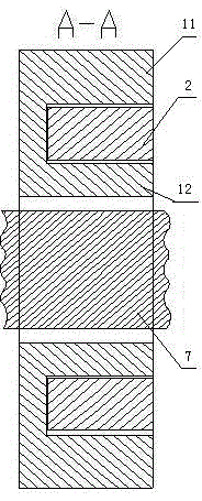
[0014] From figure 1 , figure 2 It can be seen from the figure that a pinch centering device for shafts includes a base 1, a rotating ring 2, a rotating rocker arm 3, a pressing plate 4, a locking block 5, a connecting rod 6, a pneumatic telescopic rod 8, and the like. The base 1 is provided with an outer fixing ring 11 and an inner fixing ring 12, the center of the inner fixing ring 12 is provided with a circular through hole of a shaft part, and a circular groove is arranged between the outer fixing ring 11 and the inner fixing ring 12 The rotating ring 2 is installed in the circular ring groove through the pressure plate 4; the locking blocks 5 are evenly distributed on the outer end surface of the inner fixing ring 12 around the shaft parts 7, and one end of each locking block 5 is hinged and fixed by screws On the fixed ring 12 in the base, the other end is hinged with the connecting rod 6, and the inner side of the locking block 5 is provided with an arc surface in con...


PUM


Abstract

The invention relates to a clamping centering device for shafts. The clamping centering device for shafts comprises a base, a rotating ring, lock blocks, connecting bars, a pneumatic telescopic bar, and a rotating rocker. An outer fixing ring and an inner fixing ring are arranged on the base; the center of the inner fixing ring is provided with a shaft round through hole; a circular groove is arranged between the outer fixing ring and the inner fixing ring. The rotating ring is mounted in the circular groove through press plates evenly distributed. The lock blocks around a shaft are evenly distributed on the outer end face of the inner fixing ring. One end of the rotating rocker is fixed on the outer end face of the rotating ring through a bolt; the other end of the rotating rocker is connected with the pneumatic telescopic bar; the pneumatic telescopic bar drives the rotating rocker and the rotating ring to rotate by extending or shortening, so that the lock blocks are driven to move in or out through the connecting bars so as to lock or loosen the shaft, and the shaft is centered and clamped. The clamping centering device for shafts is simple in structure, convenient to operate and adjustable in clamping size, and can operate reliably.

Description

technical field [0001] The invention relates to a pinch clamp centering device for shafts, in particular to a centering and fixing device for shafts. Background technique [0002] It is suitable for the fixed pinching clamp of shaft parts, and is an important clamping and clamping device in machine tool and shaft processing. In the production, processing and testing process of mechanical parts, it is usually necessary to support and fix the parts. Therefore, the clamp centering device is used as a fixing device to obtain a higher utilization rate. Although the various pinching devices currently used can pinch parts, they cannot be centered, and center line deviation often occurs. Therefore, there is a need for a centering and pinching device, which can not only realize the pinching function, but also realize the centering function at the same time. Contents of the invention [0003] The technical problem to be solved by the present invention is to overcome the deficienci...

Claims


Application Information

Patent Timeline
Patent Type & Authority Patents(China)
IPC IPC(8): B23Q3/00B25B11/00
CPCB23Q3/00B23Q2703/04B25B11/00
Inventor 丛建臣周先忠刘红福孙军倪培相程兆辉
Owner TIANRUN IND TECH CO LTD
Why Eureka
Try Eureka