Dual feed hydraulic lash adjuster

a hydraulic lash adjuster and dual-feed technology, applied in mechanical equipment, valve arrangements, machines/engines, etc., can solve the problems of relative short working life and premature wear of such lash adjusters, and achieve the effect of increasing the resistance to torsional side loads

Inactive Publication Date: 2006-05-23
DELPHI TECH IP LTD
View PDF8 Cites 58 Cited by
  • Summary
  • Abstract
  • Description
  • Claims
  • Application Information

AI Technical Summary

Benefits of technology

[0006]Briefly described, a dual feed hydraulic lash adjuster in accordance with the invention comprises a plunger assembly disposed within an engine bore. A one-piece plunger body includes a first chamber for forming a low-pressure oil reservoir and receiving a lash adjustment mechanism, and a second chamber open at one end and partially closed hemispherically for supporting a rocker arm and providing valve oil thereto for an auxiliary valve actuation system. The first and second chambers are separated by a transverse web, optionally having a small-diameter passage therethrough for purging of air from the lash adjustment mechanism. The plunger body is provided with a first annular collector groove and entrance port for supplying lash-adjusting oil to the first chamber, and a second annular collector groove and entrance port for supplying oil for the auxiliary valve actuation system to the second chamber. The one-piece plunger body is substantially longer than the upper section of a prior art two-piece plunger body and therefore provides a much higher resistance to torsional side loads which may be imposed on the HLA in use.

Problems solved by technology

A problem exists in some prior art HLA assemblies having a single oil feed wherein the oil pressure is varied between the two modes.
Because each of the elements is axially relatively short, the overall plunger may exhibit inferior side-load capability, resulting in relatively short working lifetimes and premature wear of such HLAs.

Method used


Image

  • Dual feed hydraulic lash adjuster
  • Dual feed hydraulic lash adjuster
  • Dual feed hydraulic lash adjuster

Examples


Embodiment Construction

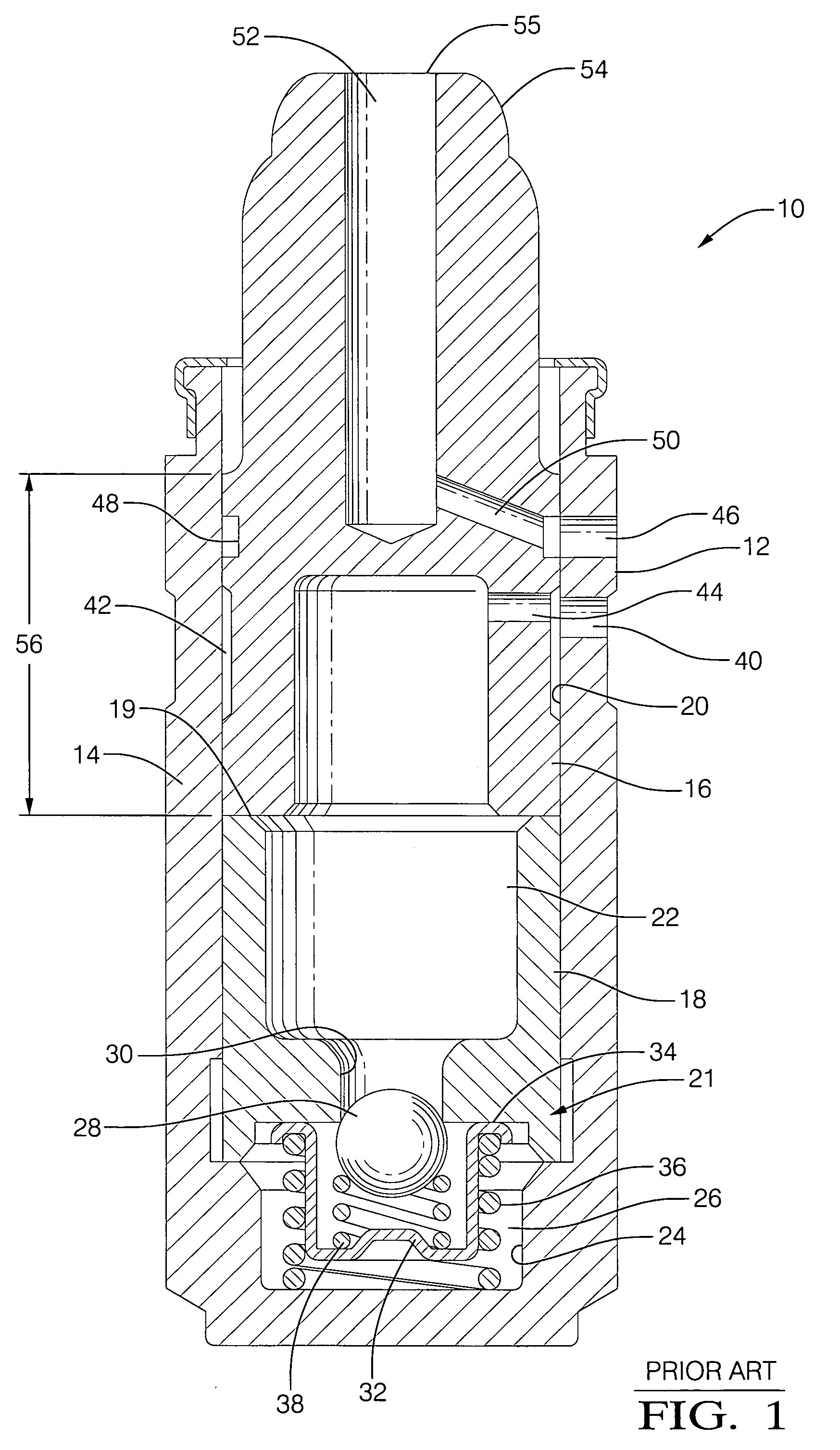
[0012]Referring to FIG. 1, a prior art dual feed hydraulic lash adjuster 10 includes a lash adjuster body 12 and a plunger assembly, generally designated as 14, which is slidingly disposed within body 12. Plunger assembly 14 includes an upper plunger element 16 and a lower plunger element 18 meeting at an interface 19, and further includes a hydraulic element assembly 21 (HEA). The plunger elements are received within body 12 in a close-fitting relationship within a bore 20 of body 12. As elements of HEA 21, upper and lower plunger elements 16,18 define a low pressure chamber 22 (reservoir) therebetween. The bottom of lower plunger element 18 forms, in cooperation with the end of a reduced diameter portion 24 of body bore 20, a high pressure chamber 26. A check valve 28 is disposed in the end of a passage 30 which connects high pressure chamber 26 and low pressure chamber 22. Check valve 28 is retained in a cage 32 which is in an interference fit within a counterbore 34 formed in lo...


PUM


Abstract

An improved dual feed hydraulic lash adjuster (HLA), for use in an internal combustion engine, comprising a hollow body and a plunger assembly disposed in a bore of the engine. A one-piece plunger body includes a first chamber for forming a low-pressure oil reservoir and receiving a lash adjustment mechanism, and a second chamber open at one end and partially closed hemispherically for supporting a rocker arm and providing valve deactivating oil thereto for an auxiliary valve actuation system. The first and second chambers are separated by a transverse web, optionally having a small-diameter passage therethrough for air evacuation. The one-piece plunger body provides a high degree of resistance to side loads which may be imposed on the HLA in use.

Description

TECHNICAL FIELD[0001]The present invention relates to hydraulic lash adjusters for combustion valves of internal combustion engines; more particularly, to a dual feed hydraulic lash adjuster for controlling the action of an auxiliary valve actuation system such as a variable lift valve mechanism; and most particularly, to an improved dual feed hydraulic lash adjuster having a one-piece plunger body for increased side-loading capability.BACKGROUND OF THE INVENTION[0002]Variable lift valve mechanisms for internal combustion engines are well known. In one example of such engines, a two-step roller finger follower rocker arm is known to pivot on a hydraulic lash adjuster (HLA) disposed on the engine block. An HLA generally comprises a slidable plunger that may be hydraulically extended to take up mechanical lash in a valve train. In an example where a valve lift change is accomplished by increasing oil pressure to the associated variable lift valve mechanism, the HLA is supplied with lo...

Claims


Application Information

Patent Timeline
Patent Type & Authority Patents(United States)
IPC IPC(8): F01L1/18F01L1/14F01L1/24
CPCF01L1/2405F01L1/185F01L13/0015F01L13/0005F01L1/267
Inventor HENDRIKSMA, NICK J.KUNZ, TIMOTHY W.
Owner DELPHI TECH IP LTD
Why Eureka
Try Eureka