Strut suspension with pivoting rocker arm

a technology of pivoting rocker arm and suspension, which is applied in the direction of resilient suspension, vehicle spring, interconnection system, etc., can solve the problems of reducing ride and handling performance, and achieve the effect of improving camber gain and roll center control, and increasing the velocities of shock pistons

Inactive Publication Date: 2007-03-06
ALTAIR ENGINEERING
View PDF25 Cites 60 Cited by
  • Summary
  • Abstract
  • Description
  • Claims
  • Application Information

AI Technical Summary

Benefits of technology

[0004]The improved strut suspension according to the present invention modifies the traditional McPherson strut suspension. The present invention improves camber gain and roll center control. The present invention provides variable caster control and progressive spring rates. The present invention also increases shock piston velocities. The improved strut suspension package according to the present invention can be bolted onto a performance or luxury version of a vehicle already equipped with a traditional strut suspension. The present invention draws the upper strut mount closer to the lower ball joint with respect to wheel movement.

Problems solved by technology

However, the manufacturing and cost benefits of this setup result in reduced ride and handling performance.

Method used


Image

  • Strut suspension with pivoting rocker arm
  • Strut suspension with pivoting rocker arm
  • Strut suspension with pivoting rocker arm

Examples


Embodiment Construction

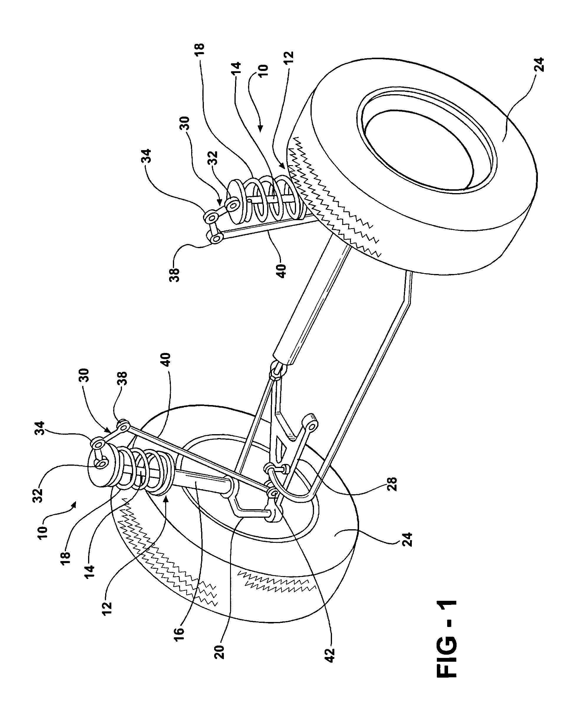
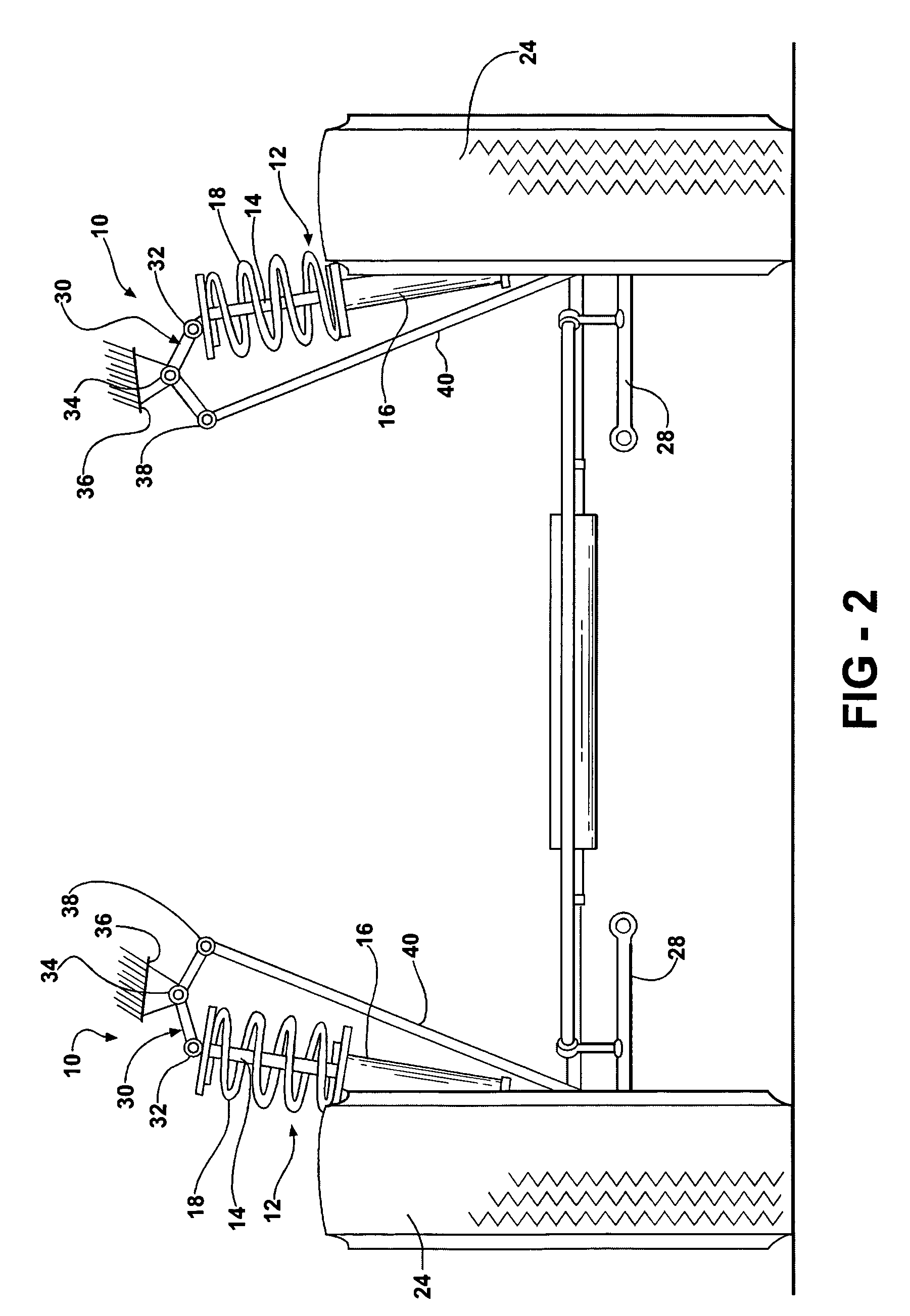
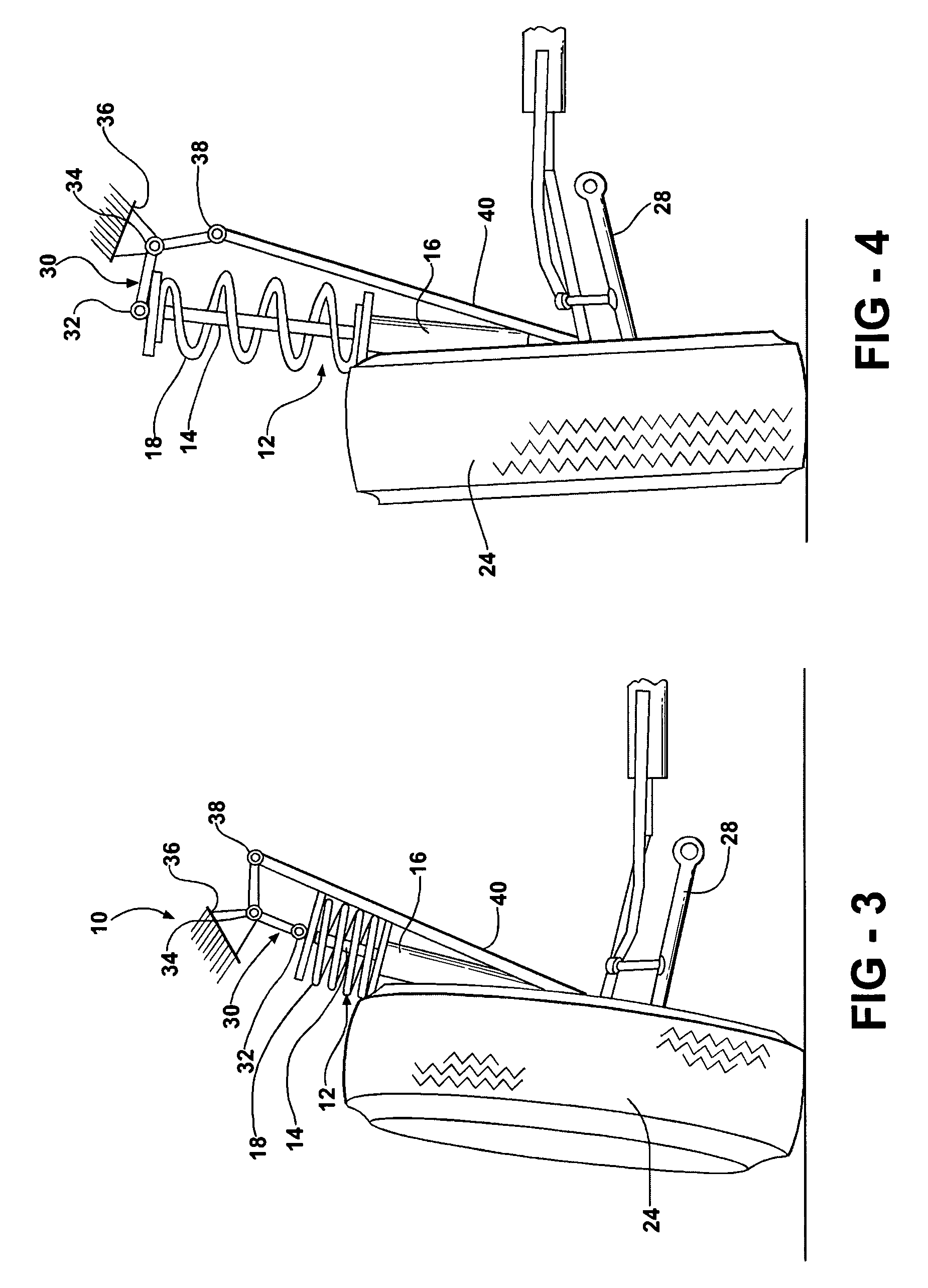
[0013]Referring now to FIGS. 1–5, an improved strut suspension 10 is illustrated. The strut suspension 10 includes a conventional shock absorber 12 including a reciprocal piston 14 within a cylinder 16 and spring 18 combination. The shock absorber assembly 12 is connected at a lower end to a steering knuckle 20. A wheel hub 22 is mounted on the steering knuckle 20 and rotatably supports the tire and rim assembly 24. The steering knuckle 20 also includes a lower ball joint 26 generally opposite from the connection of the lower end of the shock absorber assembly 12 to the steering knuckle 20. The lower ball joint 26 is connected to a transverse link 28.

[0014]The upper end of the shock absorber assembly 12 is connected to an upper strut mount or rocker arm 30. The upper portion of the shock absorber 12 is pivotally connected at 32 to one end of the rocker arm 30. The rocker arm 30 is pivotally supported at 34 to the automotive body or frame 36 shown in FIGS. 2–5. Opposite from the pivo...


PUM


Abstract

A strut suspension can include a shock-absorber/spring assembly having a lower portion mountable at one end to an upper portion of the steering knuckle. A transverse link can be connectible to the steering knuckle at a location opposite from the shock-absorber/spring assembly. A rocker arm can be supportable for pivotal movement from the vehicle body and can be pivotally connectible to the shock-absorber/spring assembly from the steering knuckle. A push rod can be pivotally connectible to the rocker arm and can extend between the rocker arm and the transverse link. The upper end of the shock-absorber/spring assembly can be connected to either an inboard or outboard portion of the rocker arm, while an upper end of the push rod is connected to the other of the outboard or inboard portion of the rocker arm.

Description

CROSS-REFERENCE TO RELATED APPLICATIONS[0001]This application claims the benefit of the Mar. 14, 2003 filing date of provisional patent application Ser. No. 60 / 454,829 which is incorporated by reference herein in its entirety.FIELD OF THE INVENTION[0002]The present invention relates to a strut suspension structure for an automotive vehicle to improve camber gain and roll center control, to provide variable caster control and progressive spring rates, while increasing shock piston velocities.BACKGROUND OF THE INVENTION[0003]The traditional McPherson strut is the most popular suspension on passenger cars today. However, the manufacturing and cost benefits of this setup result in reduced ride and handling performance. Various modifications have been proposed for strut suspension control systems, as evidenced by U.S. Pat. No. 6,267,387; U.S. Pat. No. 6,170,838; U.S. Pat. No. 5,292,149; U.S. Pat. No. 4,971,348; U.S. Pat. No. 4,756,517; and U.S. Pat. No. 4,236,728.SUMMARY OF THE INVENTION...

Claims


Application Information

Patent Timeline
Patent Type & Authority Patents(United States)
IPC IPC(8): B60G15/07
CPCB60G3/06B60G11/12B60G15/067B60G2204/421B60G2202/12B60G2204/127B60G2204/128B60G2200/142
Inventor LLOYD, JEFFREY MARSHALL
Owner ALTAIR ENGINEERING
Why Eureka
Try Eureka