A large-tonnage rock mass engineering dynamic disaster simulation test system

A technology for simulating test systems and dynamic disasters, applied in the direction of testing material strength by applying repetitive force/pulsation force, testing material strength by applying stable tension/pressure, instruments, etc., which can solve the problem of strain field range and uniformity of test equipment. It satisfies the problems of engineering practice and achieves the effect of compact structure, reducing direct damage and ensuring feasibility

Active Publication Date: 2019-06-14
YANGZHOU JIANGDU YONGJIAN
View PDF11 Cites 0 Cited by
  • Summary
  • Abstract
  • Description
  • Claims
  • Application Information

AI Technical Summary

Problems solved by technology

From the model placement method, it can be divided into two types: horizontal type and vertical type; from the model loading method, it can be divided into: it is mainly loaded by jacks, and a few are loaded by hydraulic bladders; from the way of providing reaction force: there are metal frame and foundation pit type; from the model Dimension of force: most of them are two-dimensional; From the point of view of the plane strain condition of the control model: not many are strictly achieved, and most of them adopt the quasi-plane strain condition; From the point of view of the uniformity and uniform range of the strain field generated in the model: general However, as the scale of geotechnical engineering becomes larger and larger, the engineering problems that arise become more complex, and there are more and more contents to be studied. The requirements for the scientific research design level and calculation accuracy of geotechnical engineering construction are getting higher The higher the value, the existing test equipment can no longer meet the needs of engineering practice in terms of functional loading methods, the range and uniformity of the strain field formed in the model, etc.

Method used


Image

  • A large-tonnage rock mass engineering dynamic disaster simulation test system
  • A large-tonnage rock mass engineering dynamic disaster simulation test system
  • A large-tonnage rock mass engineering dynamic disaster simulation test system

Examples


Embodiment Construction

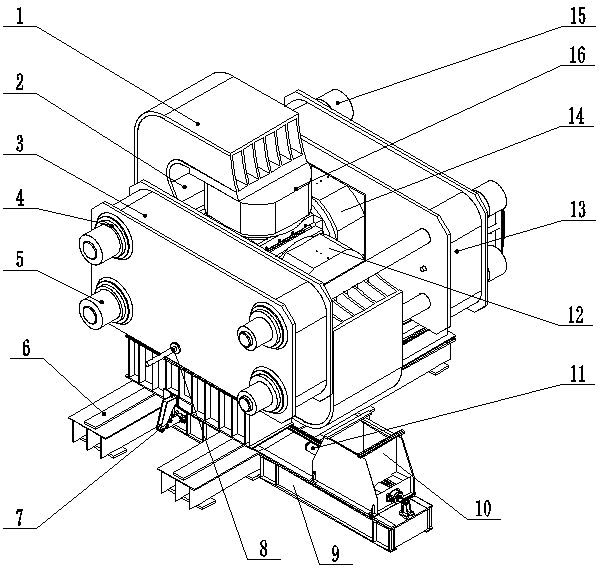
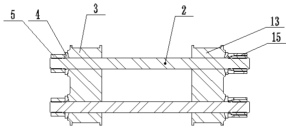
[0025] like figure 1 , 2 As shown, the large-tonnage rock mass engineering dynamic disaster simulation test system includes a fixed base 9 on which a first base 3, an annular frame 1, and a second base 13 are connected. The first base 3 and the second base 13 are respectively The connection base drives the oil cylinder 7, and is connected to the fixed base 9 through the guide rail 6. The first base 3 and the second base 13 are respectively located on the front and rear sides of the annular frame 1. The first base 3, the annular frame 1, and the second base 13 pass through The tie rod 2 is connected. One end of the tie rod 2 extends out of the first base 3 and then connects with the nut 5. A spherical pad 4 is arranged between the nut 5 and the first base 3, and the other end of the tie rod 2 extends out of the second base 13 and then connects with the hydraulic nut 15.

[0026] The moving trolley 10 is connected to the fixed base 9 through the moving trolley driving cylinder ...


PUM


Abstract

The invention provides a big-tonnage rock engineering power disaster simulation experiment system, and relates to equipment for performing experiments on big-tonnage rock. The equipment comprises a fixed base, a first base, an annular framework and a second base, wherein an upper and lower loading cylinder and a left and right loading cylinder are connected in the annular framework; a front and back loading cylinder is connected onto one side surface of the second base; each of the upper and lower loading cylinder, the left and right loading cylinder and the front and back loading cylinder comprises a static loading cylinder tube, a movable loading cylinder tube, a static loading piston rod and a movable loading piston rod; a movable loading cylinder tube installing cavity and a static loading rodless cavity are arranged in the static loading cylinder tube; the movable loading cylinder tube is arranged in a movable cylinder tube installing cavity; the static loading piston rod is arranged in the static loading rodless cavity; one end of the movable loading piston rod is provided with a movable loading piston; the movable loading piston is arranged in the movable loading cylinder tube; the other end of the movable loading piston rod penetrates through a press cover of the movable loading cylinder tube and the static loading piston rod, and is then connected with a replaceable punching head; one end, extending out of the static loading cylinder tube, of the static loading piston rod is provided with a fixing flange and a loading block. The static loading and the movable loading can be realized; the static loading and the movable loading can be also performed at the same time.

Description

technical field [0001] The present invention relates to equipment for testing large tonnage rock masses. Background technique [0002] Geomechanical model test technology is an important means to study large-scale geotechnical engineering problems. It has been widely used at home and abroad, and has played an important role in engineering scientific research design and demonstration. Many domestic and foreign units have carried out experimental research on geomechanical models, and developed supporting model test equipment of different scales. From the model placement method, it is divided into two types: horizontal and vertical; from the model loading method, it is divided into: mainly using jack loading, and a small number of hydraulic bladders are used for loading; from the way of providing reaction force: metal frame and foundation pit; from the model Force dimension points: most of them are two-dimensional; from the plane strain conditions of the control model: not man...

Claims


Application Information

Patent Timeline
Patent Type & Authority Patents(China)
IPC IPC(8): G01N3/10G01N3/36
CPCG01N3/10G01N3/36G01N2203/0003G01N2203/0005G01N2203/0016G01N2203/0048
Inventor 郭莲张均利马赛平冯建国陈传俊
Owner YANGZHOU JIANGDU YONGJIAN
Why Eureka
Try Eureka