Ultrasonic magnetic rheological composite polishing method and polisher thereof

A magnetorheological polishing and composite polishing technology, which is applied in grinding/polishing equipment, optical surface grinders, grinders, etc., and can solve the problems of inability to process concave curved surfaces and deep concave surfaces.

Inactive Publication Date: 2005-05-11
HARBIN INST OF TECH
View PDF0 Cites 108 Cited by
  • Summary
  • Abstract
  • Description
  • Claims
  • Application Information

AI Technical Summary

Problems solved by technology

However, due to the limitation of the radius of the polishing wheel, this method is more suitable for processing convex curved surfaces, planes and concave curved surfaces with large curvature radii, and cannot process concave c

Method used


Image

  • Ultrasonic magnetic rheological composite polishing method and polisher thereof
  • Ultrasonic magnetic rheological composite polishing method and polisher thereof
  • Ultrasonic magnetic rheological composite polishing method and polisher thereof

Examples


specific Embodiment approach 1

[0005] Embodiment 1: The steps of the polishing method in this embodiment are as follows: 1. Add magnetorheological polishing liquid mixed with abrasives into the stirring, constant temperature and constant viscosity control device, and fix the workpiece on the fixture of the workpiece numerical control worktable ; Start the pump, so that the magnetorheological polishing liquid mixed with abrasive flows out from the inner hole of the tool head through the circulation pipeline and so on by the pressure of the pump. 2. Start the electric spindle and ultrasonic generating device, and at the same time energize the electromagnet, so that the viscosity of the magnetorheological polishing fluid on the surface of the tool head increases rapidly within milliseconds and becomes semi-solid, forming a flexible polishing head. Rotate and vibrate at high frequency. 3. The spindle CNC workbench controls the position of the polishing head, and the processed workpiece is driven by the workpiec...

specific Embodiment approach 2

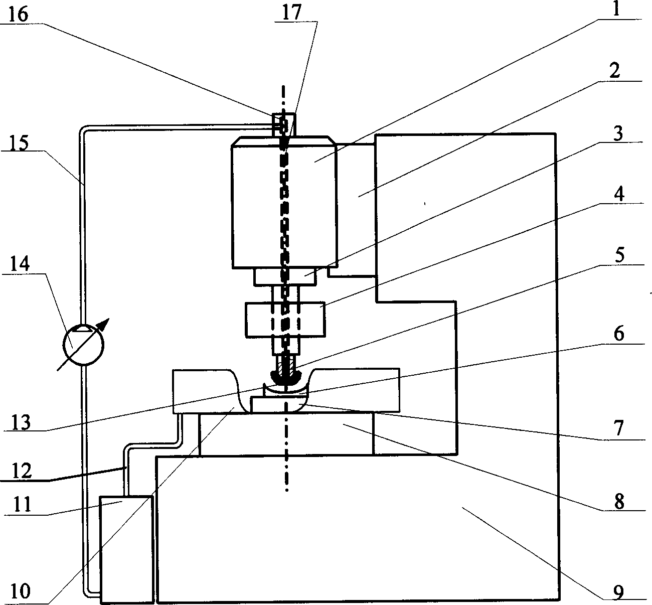
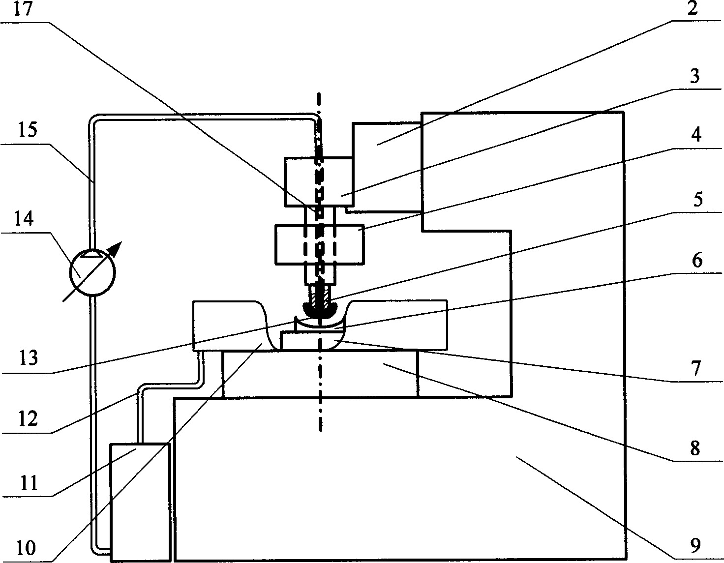
[0006] Specific implementation mode two: (see figure 1 , Figure 4 ) Ultrasonic magneto-rheological composite polishing device, which consists of electric spindle 1, spindle CNC workbench 2, ultrasonic generator 3, electromagnet 4, hollow tool head 5, fixture 7, workpiece CNC workbench 8, bed 9, recycling Tank 10, stirring, constant temperature and constant viscosity control device 11, lower circulation pipeline 12, pump 14, upper circulation pipeline 15, rotary joint 16 and internal passage 17, characterized in that the right end of the spindle CNC workbench 2 and the bed 9 The left end of the upper part is fixedly connected, one side of the electric spindle 1 is fixedly connected with the left end of the spindle CNC workbench 2, the upper end of the ultrasonic generator 3 is fixedly connected with the output end of the electric spindle 1, and the upper end of the hollow tool head 5 is connected with the ultrasonic generator The lower end of the device 3 is fixedly connected...

specific Embodiment approach 3

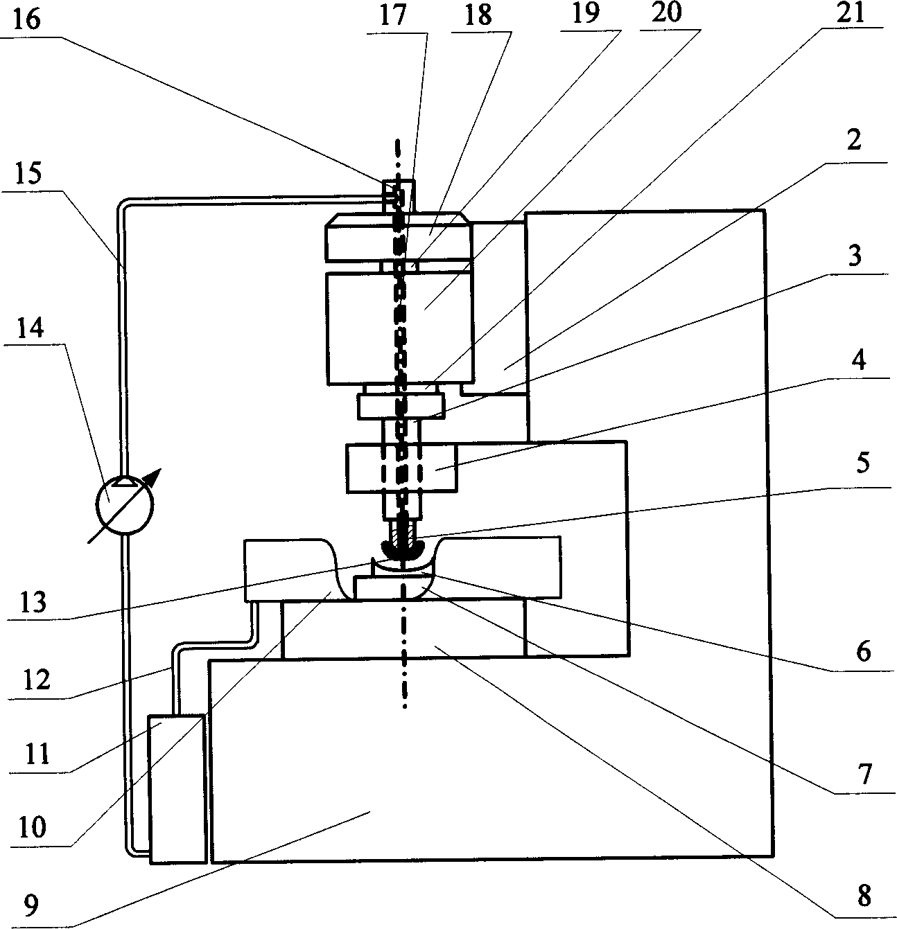
[0007] Specific implementation mode three: (see figure 2 ) The difference between this embodiment and the first embodiment is that the electric spindle 1 is replaced by the motor 18, the shaft coupling 19, the headstock 20, and the main shaft 21, and the output end of the motor 18 and the input end of the headstock 20 are connected by a coupling. The shaft device 19 is connected, the main shaft 21 on the headstock 20 is fixedly connected with the ultrasonic generator 3, and other components and connection relations are the same as those in the second embodiment.


PUM

PropertyMeasurementUnit
Magnetic inductionaaaaaaaaaa

Abstract

An ultrasonic-magnetorheologic polishing method features that the mixture of abrasive material and magnetorheologic liquid is filled in a small-diameter rotary hollow polishing head and a magnetic field is applied to it to make the magnetorheologic liquid become flexible polishing liquid on the polishing head while the ultrasonic vibration is applied to it for higher polishing effect. Its apparatus is composed of polishing head, ultrasonic generator, and electromagnet.

Description

Technical field: [0001] The invention relates to the technical fields of ultra-precision processing and optical processing, in particular to a method for ultra-precision processing the surface of optical glass and other material devices through ultrasonic magneto-rheological composite polishing and a device designed for realizing the method. Background technique: [0002] With the wide application of aspheric devices, not only the requirements for its precision and reliability are increasing, but also the ability of high-efficiency and batch production is required. As the most important process of optical precision machining, polishing is mainly to remove the surface damage layer produced by the previous processing process, correct the surface shape error, and reduce the surface roughness of the workpiece. Magnetorheological polishing (MRF) technology is a new technology for optical aspheric surface processing that has appeared abroad in recent years. In 1992, Wm I.Kordonski...

Claims


Application Information

Patent Timeline
IPC IPC(8): B24B1/00B24B13/00
Inventor 张飞虎王慧军康桂文栾殿荣
Owner HARBIN INST OF TECH
Why Eureka
Try Eureka