Groove signal restoring circuit for ISO (international standardization organization) 14443 Type A protocol

An ISO14443, signal recovery technology, applied in the direction of electrical components, automatic power control, etc., can solve the problems of competition risk, clock signal glitch, chip hidden danger, etc., and achieve the effect of reducing clock glitch and competition risk

Active Publication Date: 2013-03-06
SHANGHAI HUAHONG INTEGRATED CIRCUIT
View PDF9 Cites 7 Cited by
  • Summary
  • Abstract
  • Description
  • Claims
  • Application Information

AI Technical Summary

Problems solved by technology

[0003] Since the current decoding of the ISO14443 TypeA protocol uses an asynchronous circuit, it is susceptible to problems such as clock signal glitches during the groove signal period, competition risks, etc., resulting in hidden dangers in the chip

Method used


Image

  • Groove signal restoring circuit for ISO (international standardization organization) 14443 Type A protocol

Examples


Embodiment Construction

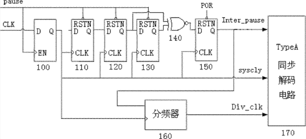
[0018] Referring to the drawings, the groove signal recovery circuit for the ISO14443 TypeA protocol includes in this embodiment: a data latch 100, a first D flip-flop 110, a second D flip-flop 120, and a third D flip-flop device 130 , data XOR gate circuit 140 , fourth D flip-flop 150 , clock divider 160 and TypeA synchronous decoding circuit 170 .

[0019] The data latch 100 uses the input groove signal pause as the enable signal, and the input clock signal CLK as the signal of its data input terminal D. After passing through the data latch 100, the clock signal during the low level period of the groove signal In this way, the clock signal burr during the groove signal period and the competition risk relationship during the groove signal change period can be effectively shielded. The output signal sysclk of the output terminal Q of the data latch 100 can be used as a clock signal of the circuit.

[0020] The input groove signal pause and the clock signal CLK are in an async...


PUM


Abstract

The invention discloses a groove signal restoring circuit for an ISO (international standardization organization) 14443 Type A protocol. The groove signal restoring circuit comprises a data latch, a first D trigger, a second D trigger, a third D trigger, a data exclusive nor gate circuit, a fourth D trigger, a clock frequency divider and a type A synchronous decoding circuit, wherein the data latch is used for enabled latched input clock signals CLK, an output end Q of the data latch outputs signals sysclk as clock signals of a circuit; the first D trigger is used for generating synchronous signals of first-grade groove signals; the second D trigger is used for generating synchronous signals of second-grade groove signals; the third D trigger is used for generating synchronous signals of third-grade groove signals, the data exclusive nor gate circuit is used for exclusive nor of output of the second D trigger and the third D trigger, the fourth D trigger is used for sampling required groove signals; the clock frequency divider is used for dividing the clock signals of the circuit; and the type A synchronous decoding circuit is used for decoding the groove signals synchronously. Affection on the circuit from clock signal burrs and race hazards can be reduced.

Description

technical field [0001] The invention relates to the field of non-contact cards, in particular to a groove signal recovery circuit for ISO14443 Type A (type A) protocol. Background technique [0002] In the ISO14443 TypeA protocol, the groove signal and the clock signal are asynchronous, and when the groove signal arrives, there may be no clock signal. In such cases, subsequent decoding circuits use asynchronous decoding. [0003] Since the current decoding of the ISO14443 TypeA protocol uses an asynchronous circuit, it is susceptible to problems such as clock signal glitches during the groove signal period, competition risks, etc., which may cause hidden dangers in the chip. Contents of the invention [0004] The technical problem to be solved by the present invention is to provide a groove signal recovery circuit for the ISO14443 TypeA protocol, which can reduce the impact of clock signal burrs and competition hazards on the circuit. [0005] In order to solve the above...

Claims


Application Information

Patent Timeline
Patent Type & Authority Applications(China)
IPC IPC(8): H03L7/10
Inventor 覃钧彦
Owner SHANGHAI HUAHONG INTEGRATED CIRCUIT
Why Eureka
Try Eureka