Balance valve

A balance valve and spool technology, applied in the field of balance valves, can solve the problems of large overall size of the balance valve, small machining allowance of the insertion hole, and few damping links of the balance valve, so as to reduce the processing cost, easy to ensure the size, and the volume compact effect

Inactive Publication Date: 2013-05-15
NINGBO JIANGDONG SIKAO TECH SERVICES
View PDF9 Cites 10 Cited by
  • Summary
  • Abstract
  • Description
  • Claims
  • Application Information

AI Technical Summary

Problems solved by technology

This puts forward high requirements on the heat treatment and material of the main valve core, which increases the processing cost
[0007] 3. Since the pilot spool of the balance valve is located inside the main spool, in order to reduce the flow resistance, it is necessary to increase the size of the pilot spool, and the size of the main spool and valve sleeve must also be increased successively, so that the balance valve Overall size is too large
The diameter of the hydraulic cylinder is fixed. If the size of the balance valve is too large, the machining allowance of the insertion hole on the hydraulic cylinder will be too small, which will cause certain difficulties in processing.
[0008] 4. There are few damping links inside the balance valve, and the stability is poor under the interference of external conditions, and it is easy to generate jitter

Method used


Image

  • Balance valve
  • Balance valve
  • Balance valve

Examples


Embodiment Construction

[0021] Embodiments of the present invention will be further described below in conjunction with the accompanying drawings.

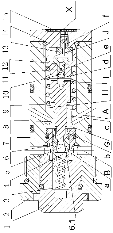
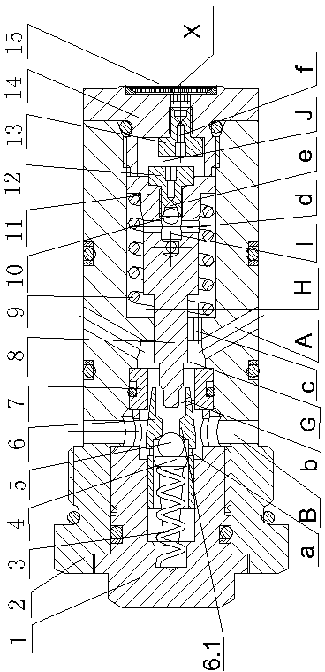
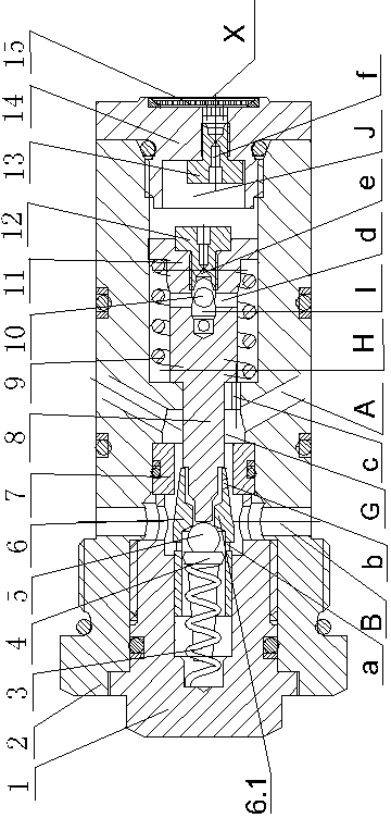
[0022] like figure 1 As shown, a balance valve includes a cylindrical valve body 2 with a first oil port A and a second oil port B and a first chamber G and a second chamber H arranged in the axial direction. The end cover 1 and screw plug 14 at both ends of the valve body 2, the valve core 6, the steel ball, the valve seat 7 and the piston 11 covered with the second spring; the rear end of the screw plug 14 is provided with a third oil port X, so A filter 15 and a second damper 13 are provided at the third oil port X, and the valve seat 7 is set in the first chamber G of the valve body 2 and is located at the first oil port A and the second oil port B between; the front section of the valve core 6 is slip-fitted in the end cover 1, the rear section of the valve core 6 is fitted in the through hole of the valve seat 7, and the valve core 6 is provided w...


PUM


Abstract

A balance valve comprises a valve body, an end cover, a plug, a valve core, a valve seat and a piston, wherein the end cover and the plug are respectively connected with the two ends of the valve body in a sealing mode. A third oil port is formed in the rear end of the plug, a filter screen and a damper are arranged at the third oil port, and the valve seat is arranged in a first cavity of the valve body and located between a first oil port and a second port. The front section of the valve core is matched in the end cover in a sliding mode, the rear section of the valve core is matched in a through-hole of the valve seat, an inner cavity which is axially penetrating is formed in the valve core, a steel ball which is matched with the inner cavity of the valve core is arranged in the valve core, a boss for axially limiting the steel ball is arranged in the inner cavity of the valve core, a first spring which is abutted against the steel ball is arranged in the inner cavity of the valve core, and the other end of the first spring is abutted in the end cover. The piston is matched in a second cavity in a sliding mode, the ladder end of the piston penetrates a cavity wall between the first cavity and the second cavity and is matched in the inner cavity of the valve core in a sliding mode, and a one-way throttling device is arranged at the rear end of the piston. The balance valve is simple in structure, compact in size and stable in working.

Description

technical field [0001] The invention relates to a hydraulic valve, in particular to a balance valve applied in a hydraulic circuit. Background technique [0002] In modern construction machinery, construction machinery and other mechanical equipment, a large number of lifting hydraulic circuits are used. Among them, the balance valve is a key hydraulic component that controls the hydraulic motor in the lifting circuit. The performance of the balance valve directly affects the performance of the main engine. . [0003] Existing balance valves are divided into plate balance valves and cartridge balance valves according to the connection mode. In order to reduce the installation space and improve system reliability in crane telescopic cylinders, cartridge balance valves are generally used. Patent No. ZL01139273.8 The invention patent titled "A Balance Valve" provides a cartridge-type balance valve. It includes a main valve and a pilot valve. Each of the above-mentioned valv...

Claims


Application Information

Patent Timeline
Patent Type & Authority Applications(China)
IPC IPC(8): F15B13/02
Inventor 陈磊
Owner NINGBO JIANGDONG SIKAO TECH SERVICES
Why Eureka
Try Eureka