Bypass disconnect switch

A technology of isolating switch and knife switch, applied in the field of bypass isolating switch, can solve the problems affecting the stability and reliability of power supply, social production, inconvenience of residents' life, etc.

Inactive Publication Date: 2015-10-14
HUBBELL ELECTRIC WUHU
View PDF5 Cites 0 Cited by
  • Summary
  • Abstract
  • Description
  • Claims
  • Application Information

AI Technical Summary

Problems solved by technology

Seriously affect the stability and reliability of power supply, and bring great inconvenience to social production and residents' life

Method used


Image

  • Bypass disconnect switch
  • Bypass disconnect switch
  • Bypass disconnect switch

Examples


Embodiment Construction

[0018] In order to deepen the understanding of the present invention, the present invention will be described in further detail below in conjunction with the accompanying drawings and embodiments, which are only used to explain the present invention and do not constitute a limitation to the protection scope of the present invention.

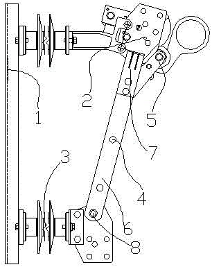
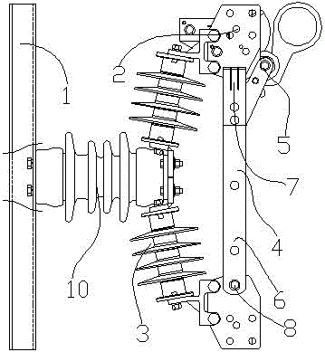
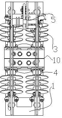
[0019] Such as figure 1 As shown in -5, the bypass isolating switch provided by this embodiment includes a base 1, a terminal board 2, an insulator 3, a conductive knife switch 4, and a knife gate latch 5; the terminal board 2 is two and is fixed on the The base 1, the two wiring boards 2 and the base 1 are connected by an insulator 3; the conductive knife switch 4 is two and one end is a fixed end 6 and the other end is a movable end 7, so The fixed ends 6 of the two conductive knife switches 4 are all arranged side by side on the base 1 through the shaft one 8, and the conductive knife switches 4 and the base 1 are connected by an insulator 3; ...


PUM


Abstract

The invention discloses a bypass disconnector which comprises a base, wiring boards, insulators, conductive disconnecting links and disconnecting link latches. The two wiring boards are fixedly arranged on the base and connected with the base through the insulators; the two conductive disconnecting links are provided with fixed ends at one ends and movable ends at the other ends, the fixed ends of the two conductive disconnecting links are parallelly arranged on the base through a first shaft, and the conductive disconnecting links are connected with the base through the insulators; the disconnecting link latches are arranged at the movable ends of the two conductive disconnecting links through a second shaft; when the disconnecting link latches are closed, the movable ends of the two conductive disconnecting links are connected with the two wiring boards respectively which are disconnected between; and when the disconnecting link latches are disconnected, the two wiring boards are connected, and the movable ends of the two conductive disconnecting links are disconnected with the two wiring boards respectively.

Description

technical field [0001] The invention relates to the technical field of electric power transmission and distribution products, in particular to a bypass isolating switch. Background technique [0002] Some functional components or equipment connected to the existing power distribution network need regular maintenance or verification, such as circuit breakers, load switches, voltage and current regulators, etc. For maintenance or calibration work, it is necessary to apply for a partial power outage of the line in advance, and to separate the equipment from the line through the operation of the front and rear switches before performing the calibration, which is time-consuming and has a large loss of power failure. [0003] For the maintenance work of this type of equipment, it is first necessary to rely on the opening and closing of the front and rear switches to separate the power outage of the equipment from the system. If it is far away, it will cause a large area of ​​powe...

Claims


Application Information

Patent Timeline
Patent Type & Authority Patents(China)
IPC IPC(8): H01H33/46H01H33/04
Inventor 郑伟
Owner HUBBELL ELECTRIC WUHU
Why Eureka
Try Eureka