Air conditioning apparatus for vehicle

A technology for air-conditioning devices and vehicles, which is applied to vehicle parts, transportation and packaging, and air handling equipment. It can solve problems such as the size of pinion gears and the position restrictions of high teeth, and achieve the effect of preventing leakage

Inactive Publication Date: 2013-06-19
KEIHIN CORP
View PDF6 Cites 0 Cited by
  • Summary
  • Abstract
  • Description
  • Claims
  • Application Information

AI Technical Summary

Problems solved by technology

Therefore, the size of the pinion and the position of the high teeth are limited, and it is necessary to pay attention to the rotation angle of the pinion when assembling the vehicle air conditioner.

Method used


Image

  • Air conditioning apparatus for vehicle
  • Air conditioning apparatus for vehicle
  • Air conditioning apparatus for vehicle

Examples


Embodiment Construction

[0028] Hereinafter, a vehicle air conditioner according to an embodiment of the present invention will be described with reference to the drawings. In addition, in the following drawings, the scale of each member is appropriately changed in order to show each member in a recognizable size.

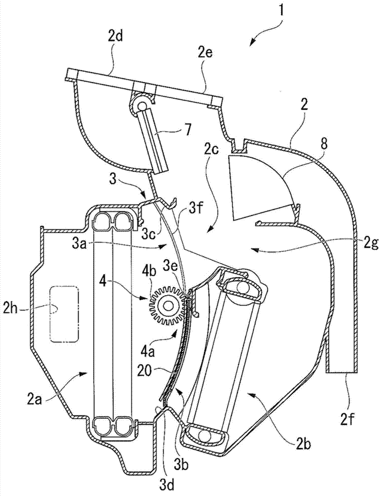
[0029] figure 1 It is a longitudinal sectional view showing a schematic configuration of a vehicle air conditioner 1 (HVAC: Heating Ventilation Air Conditioning) according to the present embodiment. As shown in the figure, a vehicle air conditioner 1 includes a casing 2 , a frame 3 , an air mixing damper 4 , an evaporator 5 , a heater core 6 , a switching mode damper 7 , and a bottom outlet mode damper 8 .

[0030] The casing 2 forms the outer shape of the vehicle air conditioner 1 according to the present embodiment, and internally has a cooling flow path 2 a provided with an evaporator 5 , a heating flow path 2 b provided with a heating core 6 , and a cooling flow path (air flow) and a ...


PUM


Abstract

An air conditioning apparatus for a vehicle that includes a frame having an opening through which an airflow passes, and a sliding door which adjusts an aperture ratio of the opening by being slid along a wall surface formed with the opening of the frame in an upstream side of the opening, wherein the sliding door includes: a shield plate to shield the airflow; and a seal member which extends from the shield plate in a sliding direction of the sliding door and is more easily bent than the shield plate, and which is bent by receiving the airflow, thereby coming into contact with the wall surface of the frame.

Description

technical field [0001] The invention relates to a vehicle air conditioner. Background technique [0002] The vehicle air conditioner is a device for supplying conditioned air adjusted in temperature and the like to a vehicle interior. This vehicle air conditioner includes a casing having an air flow path therein, and a heating core and an evaporator arranged in the middle of the air flow path. Such a vehicle air conditioner uses a heater core and an evaporator to adjust the temperature and humidity of air supplied from the outside, and supplies the adjusted air to the vehicle interior as conditioned air. [0003] Generally, a vehicle air conditioner includes a frame integrated with a housing. A plurality of openings arranged in the middle of the air flow path are formed in the frame. That is, air flows through openings provided on the frame. For example, a heating opening for supplying the heating core with air cooled by the evaporator and a cooling air opening for bypas...

Claims


Application Information

Patent Timeline
Patent Type & Authority Applications(China)
IPC IPC(8): B60H1/00F24F13/12F24F13/20
CPCB60H1/0005B60H1/00692B60H2001/00714B60H1/00028
Inventor 伊藤孝臣
Owner KEIHIN CORP
Why Eureka
Try Eureka