Strip direct splicing device

A splicing device and strip material technology, which is applied in the direction of winding strips, transportation and packaging, thin material processing, etc., can solve the problems of high cost, poor reliability of the whole machine, small parts cannot be separated, etc., and achieve high degree of automation and high pressure. The effect of reliable connection and flexible layout

Inactive Publication Date: 2013-07-31
KUNMING DINGCHENG TECH
View PDF8 Cites 5 Cited by
  • Summary
  • Abstract
  • Description
  • Claims
  • Application Information

AI Technical Summary

Problems solved by technology

Because the internal structure of the adhesive sheet feeding mechanism is relatively complicated, the whole mechanism needs to complete various motion modes such as intermittent motion, back and forth movement, circular motion, etc., and the rotating shaft of some motion modes needs to form a certain angle. A power source is realized through a relatively complex internal transmission mechanism, so there are the following disadvantages: 1) The internal transmission mechanism is too complicated, the cost is high, and there are many failures; Flexible layout; 3) Whether it is manufacturing or assembly, there are high difficulty and precision requirements; 4) The room for adjustment during debugging is very limited, which brings inconvenience to the debugging personnel; 5) Maintenance and repair are very difficult; 6) The reliability of the whole machine is poor and the efficiency is low; 7) The adhesive sheet is expensive; 8) It is easy to bring the adhesive sheet into the cigarette, which affects the quality of the cigarette

Method used


Image

  • Strip direct splicing device
  • Strip direct splicing device
  • Strip direct splicing device

Examples


Embodiment Construction

[0013] The present invention will be further described below with reference to the accompanying drawings.

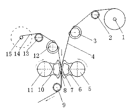
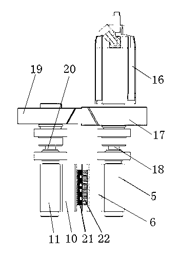
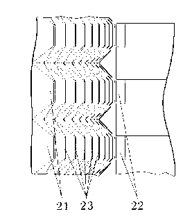
[0014] The device for direct splicing of strips provided by the present invention includes new and old tape roll support mechanisms, and is characterized in that a crimping mechanism is provided between the new and old tape roll support mechanisms, and the crimping mechanism includes a roller 11 provided with a punch 10 and a crimping mechanism. The roll 5 of the concave die 6 is set, the new strip 4 and the old strip 14 are placed between the punch 10 of the roll 11 and the concave die 6 of the roll 5, the roll shaft 20 of the roll 11 is provided with a gear 19, and the roll 5 The roller shaft 18 is provided with gears 17, 19 and 17 which mesh with two gears, wherein the axle of the gear 17 is connected with the main shaft of the power motor 16 to drive the roller pairs 11 and 5 to rotate in opposite directions through the power motor 16, the gears 19 and 17, The new st...


PUM


Abstract

The invention provides a strip direct splicing device. The strip direct splicing device comprises a new strip coil supporting mechanism and an old strip coil supporting mechanism, and is characterized in that a crimping mechanism is arranged between the new and the old strip coil supporting mechanisms, the crimping mechanism comprises a roll pair which is respectively provided with a terrace die and a concave die, both a new strip and an old strip are respectively arranged between the terrace die and the concave die, each roll shaft of the roll pair is provided with a gear, the two gears are engaged with each other, and a wheel shaft of one gear is connected with a power machine. Under the situation that no splicing auxiliary material is used, the new strip can be spliced onto the old strip on line so as to continuously supply a packing strip to a main production unit and complete the alternation between the new packing strip and the old packing strip. The strip direct splicing device is simple in structure, free from polluting main materials for producing cigarettes, free from breaking and folding the strips, reliable in crimping, high in automation degree, flexible to arrange, convenient to maintain and repair, and not only applicable to the splicing of cigarette paper and filter rod paper, but also applicable to the splicing of the packing strips in any width or any length.

Description

[0001] technical field [0002] The invention relates to a splicing device, in particular to a device for directly splicing ends of two rolls of strips without auxiliary materials, and belongs to the technical field of mechanical equipment design and manufacture. technical background [0003] In the production of cigarettes, wrapping paper, such as cigarette paper, tipping paper, filter rod forming paper, etc., needs to be wrapped around the material such as cut tobacco and filter rod to form cigarettes. In the prior art, this type of wrapping paper is placed on the reel holder in the form of a tape roll wound into a reel or a drum. The adhesive sheet is sent to the bonding position of the paper tape, and then the paper tape head of the newly installed tape roll and the tape end of the used old tape roll are bonded online at a constant speed, so as to continuously provide wrapping paper for cigarette production. , to ensure the continuous production of cigarette production....

Claims


Application Information

Patent Timeline
IPC IPC(8): B65H19/18
Inventor 李斌李小明高贤杰张华平耿利红宋柏
Owner KUNMING DINGCHENG TECH
Why Eureka
Try Eureka