Vertical pile positioning landing stage

A floating wharf and piling technology, applied in climate change adaptation, coastline protection, jetty and other directions, can solve the problems of inconvenient hoisting and installation, high difficulty in operation, harsh construction environment, etc., and achieve strong ability to absorb waves, disassembly and installation. Easy, low-cost effects

Inactive Publication Date: 2015-04-22
ZHEJIANG OCEAN UNIV
View PDF8 Cites 0 Cited by
  • Summary
  • Abstract
  • Description
  • Claims
  • Application Information

AI Technical Summary

Problems solved by technology

However, the existing marina has the following disadvantages: First, the marina structure is relatively heavy, the hoisting and installation are extremely inconvenient, the construction environment is harsh, and the operation is difficult
It can be seen that although the floating dock overcomes the defects that the structure of the floating parts is not stable enough and the floating parts are easy to shake, it has the advantages of low cost, simple structure, strong adaptability and high overall stability. The up and down movement of the floating part can change the angle relative to the horizontal plane of the floating part. However, the adjustment of the angle between the upper and lower trestles and the surface of the floating part is not flexible enough, and the upper and lower trestles are prone to malfunction and cause malfunction

Method used


Image

  • Vertical pile positioning landing stage
  • Vertical pile positioning landing stage
  • Vertical pile positioning landing stage

Examples


Embodiment 1

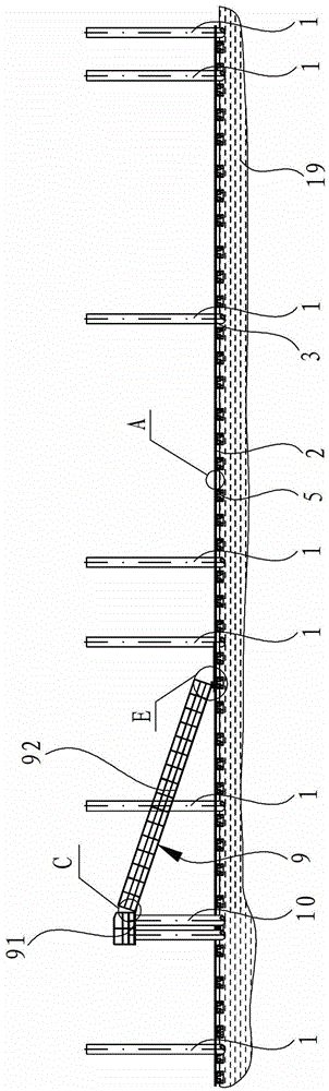
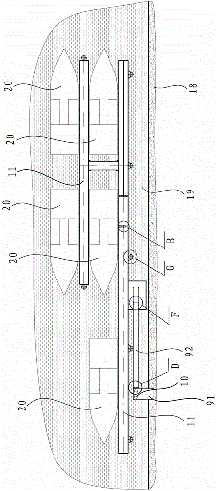
[0042] Such as figure 1 and figure 2 As shown, the piling positioning floating wharf in this embodiment includes components such as pilings 1, auxiliary pilings 10, bridge body skeleton body 6, positioning ring 3, pontoon 5, channel 9, bridge deck 11, and each module The components are fixedly connected by connecting pieces resistant to seawater and seawind erosion, and the yacht 20 is docked on the moored sea surface close to the bridge deck 11 . Wherein, the upright pile 1 and the auxiliary upright pile 10 are both arranged on the seabed and exposed to the sea surface, and can be further fixed with seawater erosion-resistant cement while being arranged on the seabed. The auxiliary pile 10 is close to the coast 18, and the channel 9 is arranged between the coast 18 and the bridge frame body 6.

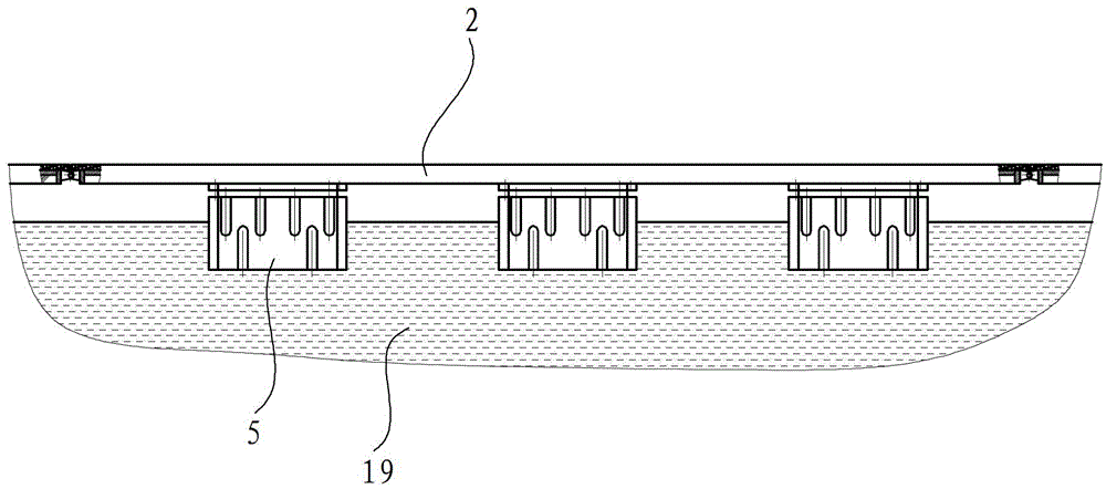
[0043] Such as Figure 3 to Figure 5 As shown, the bridge skeleton body 6 is an integral structure, which is formed by connecting multiple unit frames 2, and each unit frame 2 use...

Embodiment 2

[0047] Such as Figure 11 to Figure 17 As shown, the floating pier of this embodiment is the same as the floating pier of Embodiment 1 except that the channel structure is different. The channel 9 of this embodiment includes a fixed section 91 and a movable section 92. Between the auxiliary pile 10 , the upper end of the movable section 92 is hinged to the fixed section 91 , and the lower end of the movable section 92 is slidably connected to the bridge deck 11 . Specifically, the movable section 92 specifically includes components such as an upper beam frame 92a, a lower beam frame 92b, a step pedal 92c, a first pulley 92d, and a second pulley 92e. There are two upper beam frames 92a, which are parallel to each other and obliquely arranged on both sides of the channel 9, and the top of the upper beam frame 92a is hinged with the fixed section 91 erected at the end of the auxiliary pile 10 through a hinge shaft 93, and the lower beam frame 92b The bottom end is equipped with ...


PUM


Abstract

A vertical pile positioning landing stage comprises vertical piles, auxiliary vertical piles and a landing stage frame body. A landing stage floor board is mounted on the landing stage frame body. A passage is arranged between a coast and the landing stage frame body. The vertical pile positioning landing stage is characterized in that the passage comprises a fixed section and a movable section. The fixed section is rested between the coast and the auxiliary vertical piles. The upper end of the movable section is hinged to the fixed section. The lower end of the movable section is disposed on the landing stage floor board and can synchronously slide on the landing stage floor board while the landing stage floor board moves up and down. Positioning rings are mounted on the landing stage frame body. One positioning ring is disposed on the periphery of each vertical pile. A buffer wheel which can move along each vertical pile is mounted on the corresponding positioning ring. The vertical pile positioning landing stage has the advantages that by the buffer wheels mounted on the positioning rings, multi-direction transmission and stress dispersion of the landing stage are guaranteed when the landing stage is impacted by sea waves and when sea level moves up and down, impact of the landing stage frame body to the vertical piles is reduced, the angle between the movable section of the passage and the landing stage floor board can be adjusted flexibly along with up and down movement of the landing stage frame body, and normal operation of the passage can be constantly kept.

Description

technical field [0001] The invention relates to a combined floating wharf, in particular to a pile positioning floating wharf. Background technique [0002] Several decades ago, some scholars pointed out that the 21st century is the century of the ocean. In order to adapt to the development of the situation, China is currently stepping up the construction of all aspects of the ocean power. At present, domestic coastal production resources are gradually decreasing due to offshore production resources. In order to adapt to the development of the new situation, share the fruits of development and seize development opportunities, yachts will gradually enter the lives of ordinary people in China, and yacht marinas in coastal areas will become more and more more. However, the existing marina has the following disadvantages: firstly, the marina structure is relatively heavy, the hoisting and installation are extremely inconvenient, the construction environment is harsh, and the op...

Claims


Application Information

Patent Timeline
Patent Type & Authority Patents(China)
IPC IPC(8): E02B3/06
CPCY02A10/11
Inventor 黄添彪谢永和马志军
Owner ZHEJIANG OCEAN UNIV
Why Eureka
Try Eureka