Fiber power broadband access system and channel distribution method thereof

An access system and channel allocation technology, applied in the transmission system, digital transmission system, electrical components, etc., can solve the problems that the communication rate cannot meet the requirements of broadband communication, co-frequency and intermodulation interference, and application limitations of broadband power line communication. High commercial value and cost performance, guaranteed reliability, high reliability effect

Inactive Publication Date: 2013-10-02
WUHAN TIANCHENXIANG CLOUD DATA
View PDF4 Cites 2 Cited by
  • Summary
  • Abstract
  • Description
  • Claims
  • Application Information

AI Technical Summary

Problems solved by technology

[0003] At present, for power line broadband access multi-user network communication, broadband power line communication technology is generally used. The head end of this technology and multiple user ends use 1.8-30MHz frequency band communication at the same time, which will cause serious co-frequency and intermodulation. Interference, the communication rate cannot meet the requirements of broadband communication, which greatly limits the application of broadband power line communication

Method used


Image

  • Fiber power broadband access system and channel distribution method thereof
  • Fiber power broadband access system and channel distribution method thereof
  • Fiber power broadband access system and channel distribution method thereof

Examples


Embodiment 1

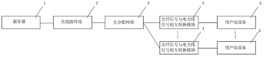
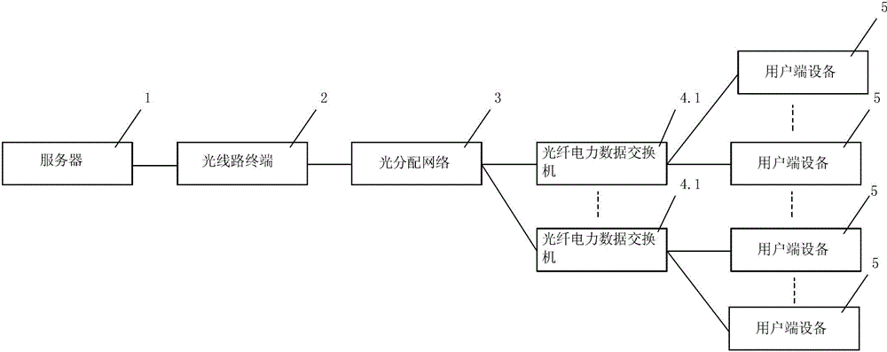
[0041] Embodiment 1: The above-mentioned optical fiber signal and power line signal conversion module 4 can be a fiber optic power data switch 4.1, and the first communication end of each fiber optic power data switch 4.1 is connected to a plurality of corresponding user end devices 5. The user end equipment 5 is a fiber optic power access user end.

[0042] The above-mentioned server 1 communicates with the optical fiber power data switch 4.1 through the fiber optic broadband network, and transmits the allocation information of user channels to the fiber optic power data switch 4.1, and the fiber optic power data switch 4.1 allocates channels to each user end device 5 through the power line. In this example, the optical distribution network 3 can output 32 optical lines to 32 fiber optic power data switches 4.1, and the fiber optic power data switches 4.1 can simultaneously couple power line signals to 6, 8 or 12 user end devices 5.

Embodiment 2

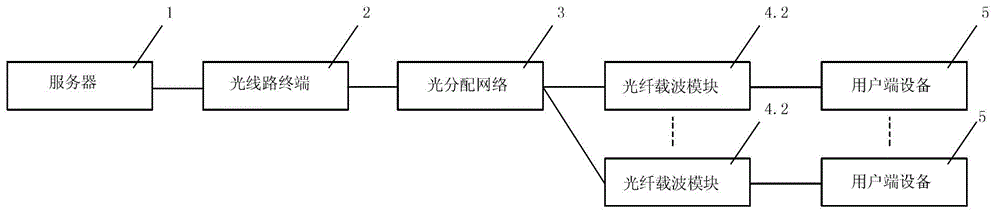
[0043]Embodiment 2: The above-mentioned optical fiber signal and power line signal conversion module 4 can also be an optical fiber carrier module 4.2, and the first communication end of each optical fiber carrier module 4.2 is connected to a corresponding user end device 5. The user end equipment 5 is a fiber optic power access user end.

[0044] The above-mentioned server 1 communicates with the fiber optic carrier module 4.2 through the fiber optic broadband network, and transmits the allocation information of user channels to the fiber optic carrier module 4.2, and the fiber optic carrier module 4.2 allocates channels to each user end device 5 through the power line. In this example, the fiber optic carrier module 4.2 is located in the fiber optic power meter, and the general meter box can accommodate 8 fiber optic power meters, and the optical distribution network 3 can output 8 optical lines to 8 fiber optic carrier modules, and the fiber optic carrier module 4.2 and the ...


PUM


Abstract

The invention relates to a fiber power broadband access system. The fiber power broadband access system comprises multiple fiber signal and power line signal conversion modules, user end equipment connected with a first communication end of each fiber signal and power line signal conversion module, and a server, a light line terminal and a light distribution network which are connected sequentially, wherein the light distribution network is connected with second communication ends of the multiple fiber signal and power line signal conversion modules. The fiber power broadband access system realizes physical layer channel distribution in multi-user broadband power line communication, solves problems of co-frequency interference and cross-frequency interference among different users, so operation of the broadband power line communication can be really realized. The fiber power broadband access system can facilitate four-network fusion, can further expand intelligent household application and has great business values and cost performance.

Description

technical field [0001] The invention relates to a channel allocation method for a broadband access user end, in particular to an optical fiber power broadband access system and a channel allocation method of the system. technical background [0002] Power Line Communication (PLC, Power Line Communication) technology is a communication method that uses power lines to transmit data and media signals. This technology is to modulate the high-frequency signal carrying information on the power line frequency signal, and then demodulate the high-frequency signal from the power frequency signal with an adapter that receives information and transmit it to a computer, telephone or TV to realize information transmission. . The biggest advantage of this technology is that no rewiring is required. It can carry multiple services such as data, voice and video on the existing power line, and promote the integration of four networks. End users only need to plug in the power plug to access...

Claims


Application Information

Patent Timeline
Patent Type & Authority Applications(China)
IPC IPC(8): H04L12/28H04L12/24H04L12/911
Inventor 王良藩彭斌
Owner WUHAN TIANCHENXIANG CLOUD DATA
Why Eureka
Try Eureka