High-property high-pressure three-screw pump

A three-screw pump, high-performance technology, applied in the direction of pumps, rotary piston pumps, rotary piston machines, etc., can solve the problems of difficult machining of screw holes, difficulty in ensuring machining accuracy, and decreased volumetric efficiency, so as to reduce casting defects , the effect of volumetric efficiency improvement and inner hole clearance reduction

Active Publication Date: 2014-04-09
黄山工业泵制造有限公司
View PDF6 Cites 7 Cited by
  • Summary
  • Abstract
  • Description
  • Claims
  • Application Information

AI Technical Summary

Problems solved by technology

The above structure has the following problems: ①In general, the higher the delivery pressure of the screw pump, the longer the effective length of the screw is required. Since the bushing 18 and the driven screw 19 are both integral structures, with the bushing 18 and the driven screw The longer the length of 19, the more difficult it is to process and the more difficult it is to ensure the machining accuracy, especially the processing of the screw holes at both ends of the bushing is extremely difficult; Deflection deformation will inevitably occur during processing and operation, which affects the meshing gap between it and the helical surface of the driving screw 1, and also affects the gap between the outer circle of the helical surface of the driven screw 19 and the inner hole of the bushing 18
If the gap is too small, it is easy to cause the product to "hold the shaft" or even get stuck during operation; if the gap is too large, the volumetric efficiency of the pump will decrease
It is precisely because of the above two problems that the traditional high-pressure three-screw pump can only be applied to working conditions below 8.0MPa (individual pumps can reach up to 10.0MPa)

Method used


Image

  • High-property high-pressure three-screw pump
  • High-property high-pressure three-screw pump
  • High-property high-pressure three-screw pump

Examples


Embodiment Construction

[0019] The present invention will be further described through the embodiments below in conjunction with the accompanying drawings.

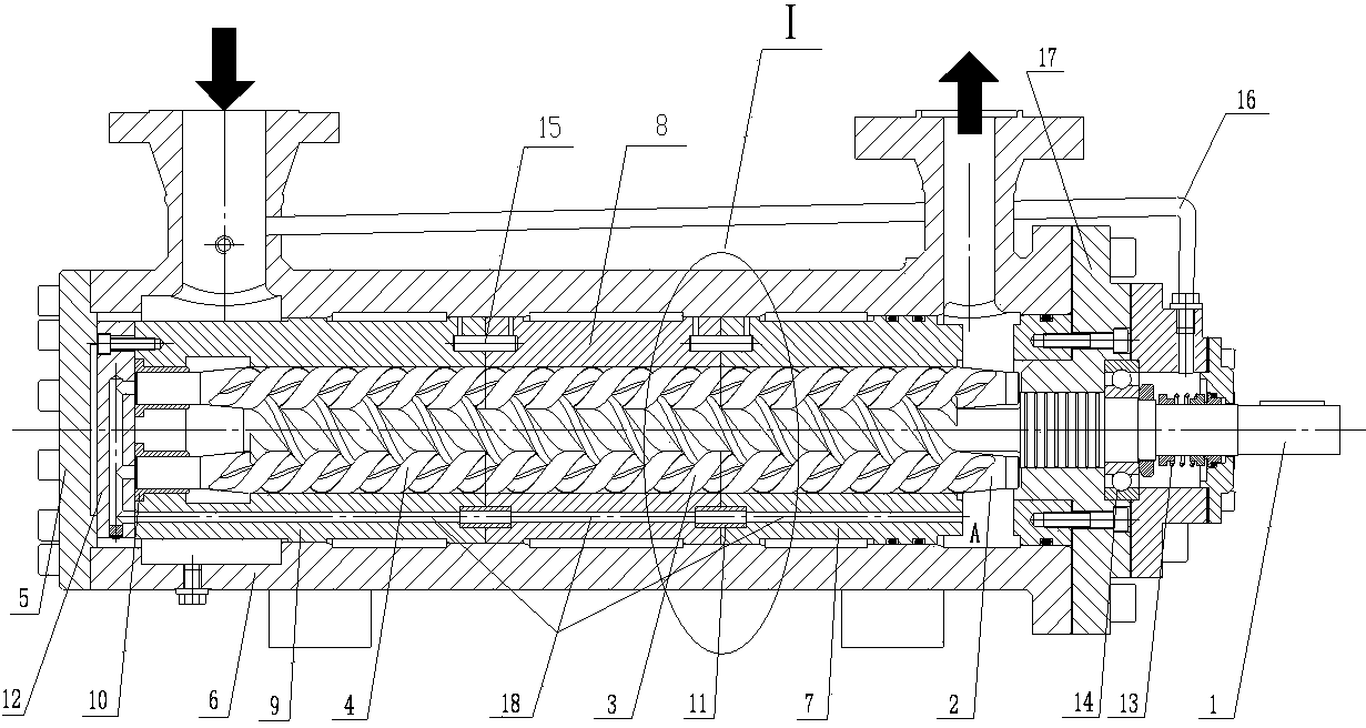
[0020] see figure 1 A high-performance high-pressure three-screw pump includes a pump body 6, a driving screw 1 and two driven screws 19, a bushing 18 is installed axially inside the pump body 6, and the driving screw 1 and two driven screws 19 are co-located on the bushing 18 Inside; the axial ends of the pump body 6 are respectively equipped with a front end cover 17 and a rear end cover 5; the length-to-diameter ratio of the helical section of the driving screw 1 is more than 8, and the driving screw 1 on the side of the driving end is installed on the front end cover through a bearing 14 17, a mechanical seal 13 is installed on the active screw rod 1 in the front end cover 17, and the driving end of the active screw rod 1 extends to the outside of the front end cover 17, and the driving end of the active screw rod 1 in the front end cover 1...


PUM


Abstract

The invention relates to a high-property high-pressure three-screw pump. The high-property high-pressure three-screw pump comprises a pump body, a liner, a driving screw and two driven screws, wherein the liner is formed by connecting three sections of split liners in sequence; three matching holes matched with the driving screw and the driven screws are respectively formed in the both axial ends of each section of the split liner; the three sections of the split liners respectively comprise a front liner, a middle liner and a rear liner; each driven screw consists of a front section screw, a middle section screw and a rear section screw; the outer ends of the front section screws of the two driven screws are respectively arranged on the pump body and are in the shape of a cantilever; the outer ends of the rear section screws of the two driven screws are respectively arranged in the three matching holes in the outer end of the rear liner through axle sleeves in the cantilever shape; the both ends of the middle section screw of each driven screw respectively are in contact with the corresponding front section screw and rear section screw, so that the middle section screws are in a shape of a float rod. According to the high-property high-pressure three-screw pump provided by the invention, the highest working pressure is 20.0MPa, the machining difficulty is reduced, and the matching precision among parts is improved, so that the reliability and the volume efficiency of the pump can be improved.

Description

technical field [0001] The invention belongs to the technical field of displacement screw pumps, in particular to a high-pressure three-screw pump. Background technique [0002] Compared with traditional centrifugal pumps, gear pumps, and reciprocating pumps, three-screw pumps, which belong to the category of industrial pumps, have outstanding advantages such as stable flow, small pressure fluctuations, high efficiency, and long service life. They have been widely used in metallurgy, machinery, electric power, and ships. be applied in other industries. However, the traditional high-pressure three-screw pump generally has low pressure, which makes it unable to meet the use requirements in some fields such as the transportation of liquid fuel from low pressure to high pressure in power plants. In addition, under high pressure conditions, the effective screw section of the three-screw pump must be lengthened, which makes it very difficult to process the integrated bush and dri...

Claims


Application Information

Patent Timeline
Patent Type & Authority Applications(China)
IPC IPC(8): F04C2/107
Inventor 程爱华程飞
Owner 黄山工业泵制造有限公司
Why Eureka
Try Eureka