Check patentability & draft patents in minutes with Patsnap Eureka AI!

Ophthalmic apparatus and control method therefor, and camera

A kind of equipment and ophthalmology technology, applied in the direction of eye testing equipment, ophthalmoscope, medical science, etc., can solve the problem of automatic focusing process of the structure without explaining the brightness value

Inactive Publication Date: 2014-05-14
CANON KK
View PDF6 Cites 3 Cited by
  • Summary
  • Abstract
  • Description
  • Claims
  • Application Information

AI Technical Summary

Problems solved by technology

Also, with regard to the fundus camera disclosed in Document 2, there is no description of the structure for processing the brightness value that changes according to the position of the focus lens and the autofocus process using the contrast value

Method used


Image

  • Ophthalmic apparatus and control method therefor, and camera
  • Ophthalmic apparatus and control method therefor, and camera
  • Ophthalmic apparatus and control method therefor, and camera

Examples


no. 1 example

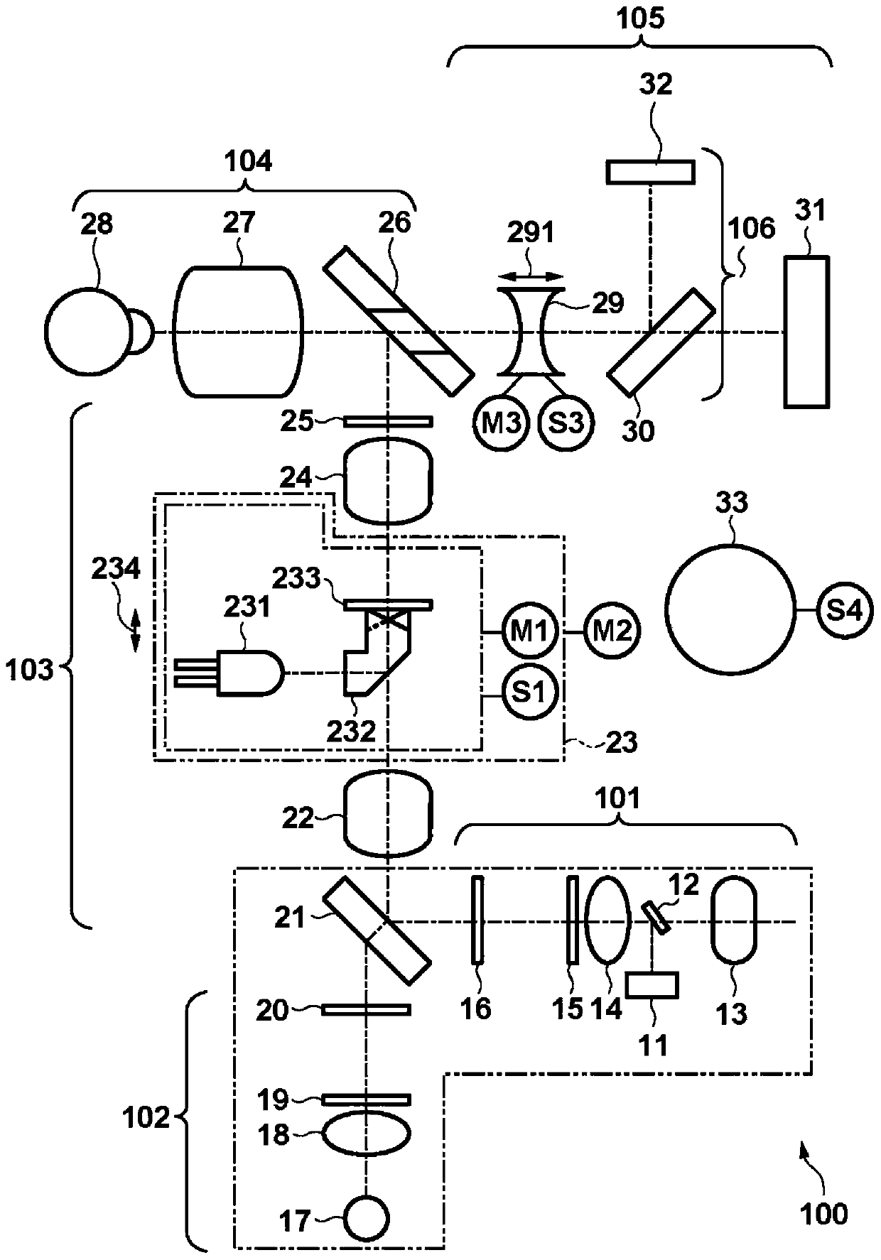
[0027] will refer to Figure 1 to Figure 9 A fundus camera as an ophthalmic apparatus according to a first embodiment is described. First refer to figure 1 Describe the schematic structure of this camera. figure 1 is a schematic diagram for explaining the structure of the fundus camera according to the first embodiment.

[0028] The fundus camera 100 roughly includes an imaging light source unit 101 , an observation light source unit 102 , an illumination optical system 103 , an imaging / illumination optical system 104 , an imaging optical system 105 , and an internal fixation lamp unit 106 . The light beam emitted from the imaging light source unit 101 or the observation light source unit 102 illuminates the fundus of the subject through the illumination optical system 103 and the imaging / illumination optical system 104 . An image of the fundus of the eye is formed on the image sensor 31 via the imaging / illumination optical system 104 and the imaging optical system 105 .

...


PUM


Abstract

The invention relates to an ophthalmic apparatua and a control method thereofor, and a camera. The ophthalmic apparatus includes an illumination optical system which projects an illumination light beam from an illumination light source onto the fundus of the eye to be examined and an imaging optical system which guides reflected light from the fundus to imaging part. The ophthalmic apparatus calculates the contrast value of the fundus image formed by the imaging part, and focuses the imaging optical system on the fundus by moving a focus lens in the optical-axis direction of the imaging optical system based on the contrast value obtained by the calculation. The apparatus adjusts the contrast value obtained by the above calculation based on the position of the focus lens in the optical-axis direction.

Description

technical field [0001] The present invention relates to an ophthalmic device and a control method for the device. Background technique [0002] In general, a fundus camera projects a divided focus index on a pupil of an eye to be inspected at the time of a focusing operation in order to detect a focus position on the fundus of the eye. An operator performs focusing while observing a positional relationship between reflected focus index images via a focus lens arranged in the imaging optical system. It is also known to take focus index images projected to the eye and reflected, and to perform an automatic focus adjustment operation based on the positional relationship between the focus index images. [0003] However, due to the influence of aberrations caused by astigmatism or the like in the optical system inside the eye, setting the focus index image only in a predetermined positional relationship (aligning them on a straight line) causes a Error in focus position. This ...

Claims


Application Information

Patent Timeline
Patent Type & Authority Applications(China)
IPC IPC(8): A61B3/15A61B3/12
CPCA61B3/14A61B3/12
Inventor 大番英之相川聪中野喜隆齐藤洋平
Owner CANON KK
Features
  • R&D
  • Intellectual Property
  • Life Sciences
  • Materials
  • Tech Scout
  • Unparalleled Data Quality
  • Higher Quality Content
  • 60% Fewer Hallucinations
Learn More