Baler and method of baling

A technology of a baler and a rotary drive mechanism, which is used in the baler and baling fields to achieve the effect of high plunger force and high density

Active Publication Date: 2014-05-28
KUHN GELDROP
View PDF8 Cites 5 Cited by
  • Summary
  • Abstract
  • Description
  • Claims
  • Application Information

AI Technical Summary

Problems solved by technology

Adjusting the biasing force applied to the side / top plate force based on the plunger force will cause the same problems and drawbacks

Method used


Image

  • Baler and method of baling
  • Baler and method of baling
  • Baler and method of baling

Examples


Embodiment Construction

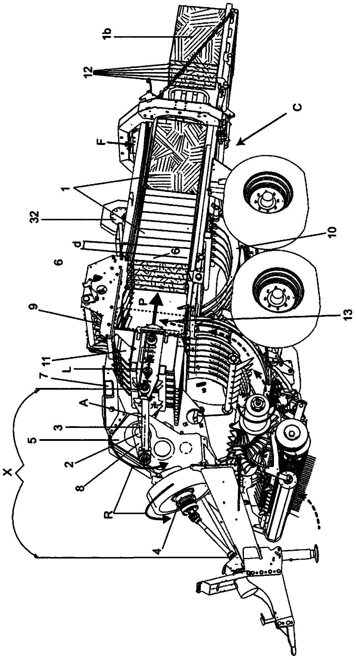
[0038] figure 1 The baling machine or baler shown in includes a baling chamber C and a plunger D that can be driven into the baling chamber C in a reciprocating manner. The baler also includes a pick-up mechanism M for picking up cut bale material, such as grass and straw, from the ground, a feed mechanism N for feeding the bale material into the baling chamber C, and a mechanism for feeding the drive from the tractor ( not shown) drive output to drive train X for plunger D. These components are all conventional and may be as described, for example, in US Patents 4,074,623 and 4,142,746. The tying machine also includes a binding device E for binding with a binding hemp rope. The binding means may for example be as described in US4074623.

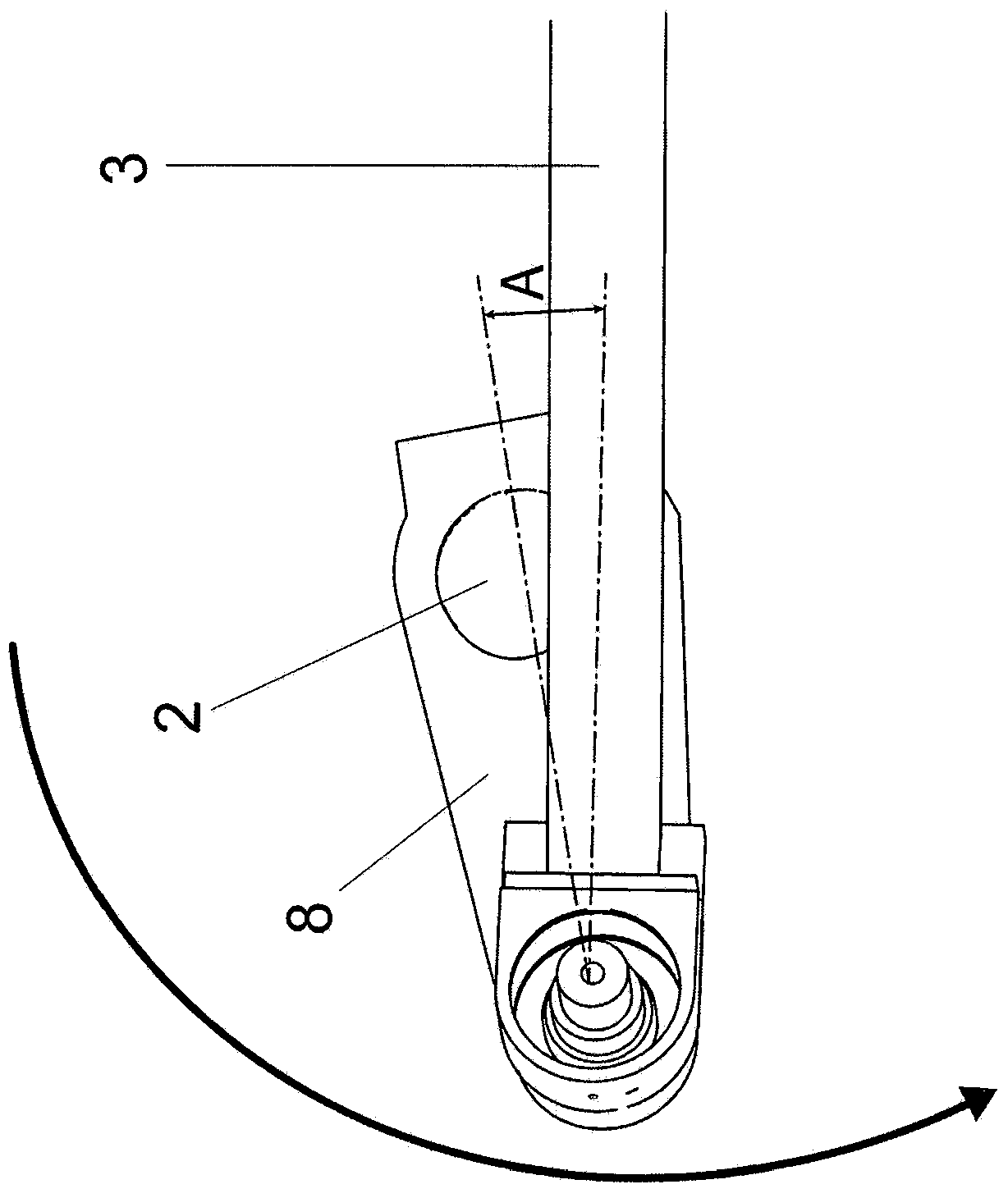
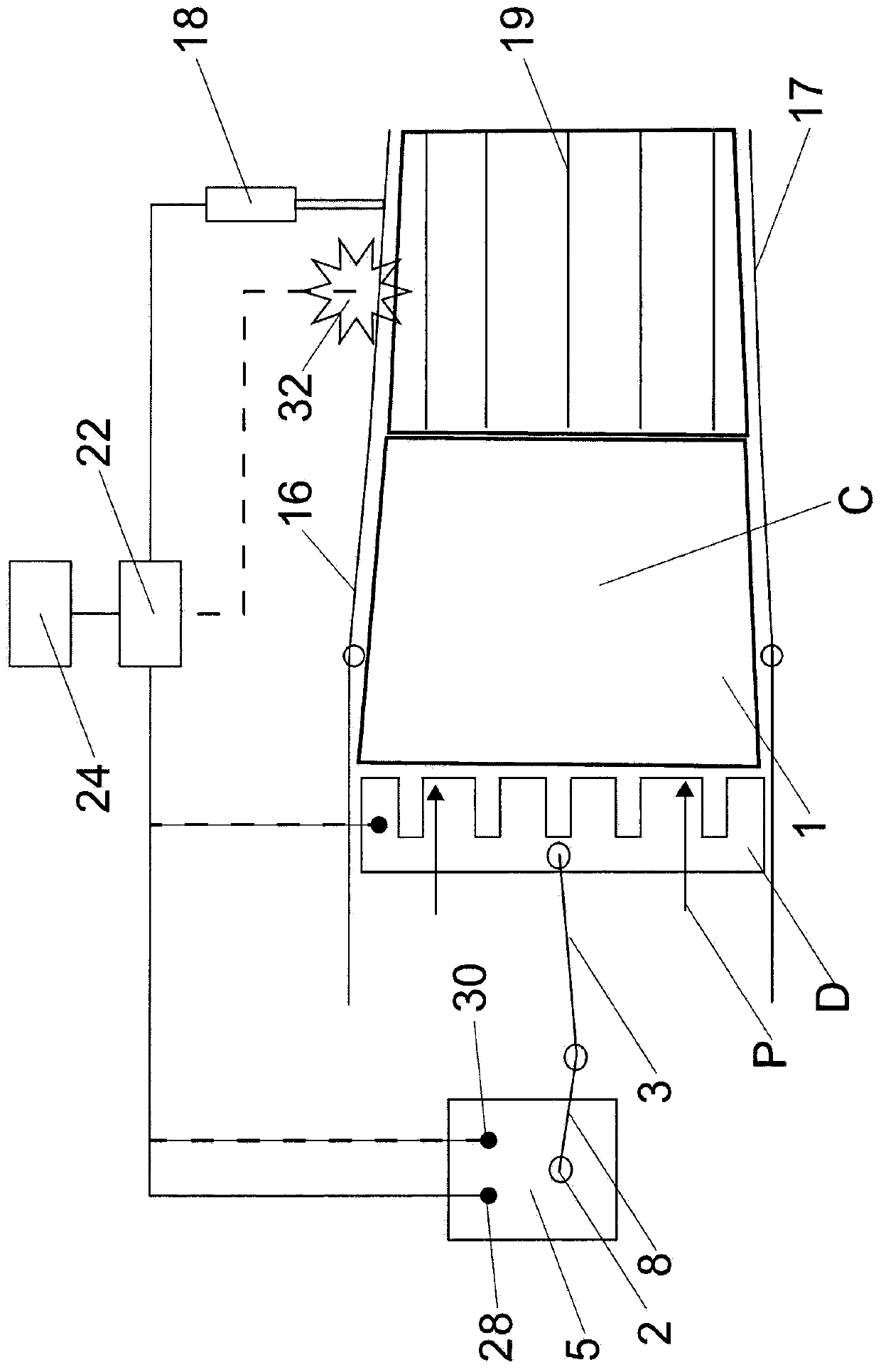
[0039] The baling chamber C comprises an open-ended bale-forming channel through which the bale material 1 is pushed by the reciprocating plunger D. In this example, the plunger D is driven from the rotary drive shaft 2 via the crank 8 a...


PUM


Abstract

A baler comprises a baling chamber (C) that includes a bale-forming channel having at least one adjustable friction control element (16), a plunger (D) mounted within the channel and a rotary drive mechanism (8) for driving reciprocating movement of the plunger. A control system (22) controls operation of the baler, the control system being configured to determine an actual maximum torque value associated with the rotary drive mechanism (8), compare the actual maximum torque value with a selected desired maximum torque value and adjust the friction control element (16) to regulate the actual maximum torque value according to the desired maximum torque value.

Description

technical field [0001] The present invention relates to baling machines and methods of baling, particularly but not exclusively to baling crops. Background technique [0002] For efficient transport and storage, agricultural products such as hay, straw and silage can be compressed into parallelepiped-shaped bales called 'square' bales. After compressing the bale material the shape and compression of the bale is maintained by tying with twine around the compressed bale material. The ends of the twine are then knotted together. [0003] Typically, compression of the bale material is performed by a reciprocating ram baler. Typical balers of this type are described in US Patents 4,074,623 and 4,142,746 to the Hesston Company. The baler is sort of like figure 1 The baler shown in , which includes a baling chamber C having an open-ended passage through which bale material is pushed by a reciprocating plunger D. The plunger is driven in a substantially linear direction L betwe...

Claims


Application Information

Patent Timeline
Patent Type & Authority Applications(China)
IPC IPC(8): A01F15/08B30B9/30
CPCA01F15/0841B30B9/3007A01F15/0825A01F15/04
Inventor L·H·M·范阿姆斯特尔D·C·M·阿克曼斯
Owner KUHN GELDROP
Why Eureka
Try Eureka