Method for accurately positioning optical cable line fault points through optical cable artificial faults

A line fault, precise positioning technology, applied in the direction of electromagnetic wave transmission system, electrical components, transmission system, etc., can solve the problem of low positioning accuracy, achieve the effect of improving positioning accuracy, saving manual training, and saving manpower and material resources

Inactive Publication Date: 2014-06-11
郑瑜
View PDF3 Cites 20 Cited by
  • Summary
  • Abstract
  • Description
  • Claims
  • Application Information

AI Technical Summary

Problems solved by technology

[0006] The technical problem to be solved by the present invention is to overcome the shortcomings of existing cable line fault point location that requires accurate and perfect cable line maintenance data to realize the location of the optical cable line fault point, and the positioning accuracy is not high, and to provide a method that does not require accurate and detailed The method of accurately locating the fault point of the optical cable line can be realized by the maintenance data of the optical cable line

Method used


Image

  • Method for accurately positioning optical cable line fault points through optical cable artificial faults
  • Method for accurately positioning optical cable line fault points through optical cable artificial faults
  • Method for accurately positioning optical cable line fault points through optical cable artificial faults

Examples


example 1

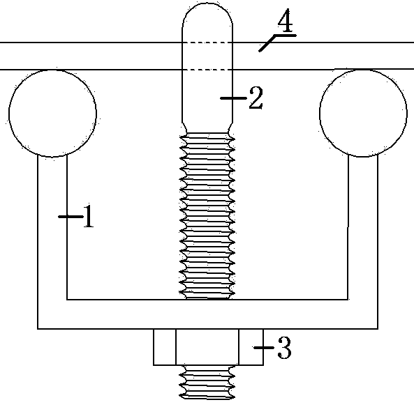
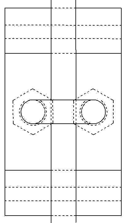
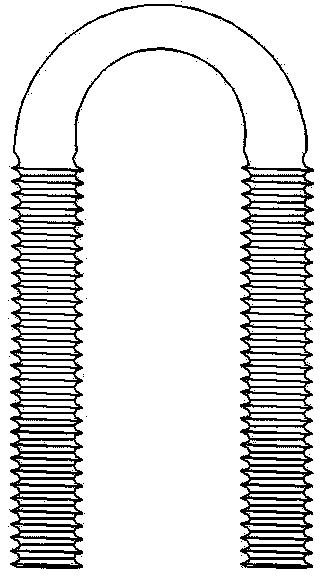
[0039] In this example, the OTDR uses Yokogawa AQ7275, the optical cable adopts GYTS-24B1 optical cable, the optical fiber adopts ITU-T G.652 standard single-mode optical fiber, and the diameter of the optical cable is 11mm. The schematic diagram of the optical cable structure is as follows figure 1 shown. The optical cable cards are all metal, and the structure is as follows: image 3 The shown includes bracket 1, U-shaped rod 2, and nut 3, in which a cylinder is fixed at both ends of bracket 1, and the radius of the cylindrical surface is 16 mm, which is greater than the critical curvature radius of the optical fiber. There are two round holes on the center line of the base of bracket 1, and the U-shaped rod 2 can be pierced through the round hole, the U-shaped rod 2 has threads, and the rotating nut 3 can make the U-shaped rod 2 move up and down. The side height of the bracket 1 is 46mm, and the bottom surface width is 80mm. After reaching the bottom end, the optical cable...


PUM


Abstract

The invention discloses a method for accurately positioning optical cable line fault points through optical cable artificial faults. The characteristics of the optical fiber extra length of an optical cable and the elasticity and the toughness of the optical cable are fully utilized, external force is applied to a certain point of the optical cable to make the optical cable bent and generate optical fiber macrobend losses, the optical cable artificial faults are formed and serve as positioning reference points, the relative distance between the optical cable line fault points and the poisoning reference points is measured through an OTDR, and then the optical cable line fault points can be accurately positioned. Complex formula conversion between the optical cable fiber length, the cable length and the ground length is not needed, and various optical cable fault points under the condition that source materials of an optical cable line are incomplete and especially optical cable concealed fault points can be accurately positioned. In the optical cable artificial faults manufacturing process, no substantial damages are caused to the optical cable or optical cable inner fibers at all, and the method has the advantages of being safe, simple, efficient, and easy to popularize.

Description

technical field [0001] The invention relates to a method for precisely locating a fault point of an optical cable, in particular to a method for accurately locating fault points of various optical cable lines, especially a concealed fault point of an optical cable, under the condition that maintenance information of the optical cable line is inaccurate. Background technique [0002] The traditional optical cable line fault location method uses accurate and complete optical cable line maintenance data as the basis for fault measurement and location, and uses OTDR to test the line to determine the nature and location of the fault. For obvious optical cable faults, for example, when the optical cable line is blocked due to external forces such as natural disasters or external construction, it is generally easier for inspection and repair personnel to find it according to the location provided by the tester. However, for concealed faults, the distance from the fault point to the...

Claims


Application Information

Patent Timeline
Patent Type & Authority Applications(China)
IPC IPC(8): H04B10/071
Inventor 郑瑜
Owner 郑瑜
Why Eureka
Try Eureka