Ultrasonic Endoscope

An ultrasonic and endoscope technology, applied in the field of ultrasonic endoscope, can solve the problems of inability to handle the flow of instruments, difficulty in current flow, and thicker diameter of the insertion part.

Active Publication Date: 2014-07-09
FUJIFILM CORP
View PDF5 Cites 21 Cited by
  • Summary
  • Abstract
  • Description
  • Claims
  • Application Information

AI Technical Summary

Problems solved by technology

[0015] However, since the operating metal wire is thin, the on-resistance is high and current is difficult to flow
Therefore, even if the operation metal wire is electrically connected to the ground of the operation part, the leakage current from the treatment tool may not flow properly to the ground.
[0016] On the other hand, when the operation metal wire is thickened to facilitate the flow of electric current, there is a problem that the diameter of the insertion part becomes thicker.

Method used


Image

  • Ultrasonic Endoscope
  • Ultrasonic Endoscope
  • Ultrasonic Endoscope

Examples


Embodiment Construction

[0038] Hereinafter, embodiments of the present invention will be described with reference to the drawings.

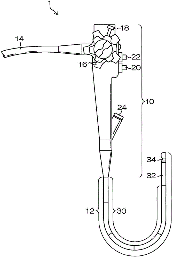
[0039] figure 1 It is an overall view of an ultrasonic endoscope 1 to which the present invention is applied.

[0040] Ultrasonic endoscope 1 in this figure (hereinafter simply referred to as endoscope 1) includes: an operation unit 10 that is grasped by a person performing an operation to perform various operations; an insertion unit 12 that is inserted into a patient's body cavity; A processing device (not shown) of the endoscope system; and a general-purpose cord 14 for connecting the endoscope 1 to a system constituting device such as a light source device.

[0041] The operation unit 10 is provided with various operation members operated by the person performing the operation, for example, an angle knob (angle adjustment knob) 16, an upright operation lever 18, an air / water supply button 20, and a suction button 22 are provided. Wait.

[0042] In addition, the o...


PUM


Abstract

The present invention provides an ultrasonic endoscope which enables a leakage current to a standing table to diffuse appropriately to an earth wire when the high frequency disposal appliances are used. The standing table (60) arranged at the front end part (34) of the ultrasonic endoscope(1) and a driving mechanism are assembled into standing table components (72) integrally via a conductive part, and are accepted and kept by an accepting part formed by an insulating front end part main body (36). An angle ring (a front end ring) (250) is embedded at the frontmost end of a bending part (32) at the periphery at the base end side of the front end part main body (36), the front end ring (250) and the standing table components (72) (an assembly main body 80) are connected via a conductive screw (270) embedded in a conduction hole (220). The angle ring is connected with the earth wire, so that the leakage current leaking to the standing table (60) from the disposal appliance is discharged to the earth wire via the angle ring of the bending part (32).

Description

technical field [0001] The present invention relates to an ultrasonic endoscope, and more particularly to an ultrasonic endoscope including a treatment instrument erecting stand for erecting a treatment instrument derived from a treatment instrument lead-out portion at a distal end portion of an insertion portion. Background technique [0002] Conventionally, in ultrasonic endoscopes, there is known a structure in which an upright stand is provided at the front end of an insertion portion inserted into a body cavity, and the treatment tool passed through the treatment tool insertion channel is inserted from the front end by the upright stand. The treatment tool pulled out by the lead-out unit stands up, and the pulling-out direction of the treatment tool can be adjusted by changing the stand-up angle of the stand (for example, refer to Patent Document 1). [0003] According to the endoscope of Patent Document 1, an erecting stand is provided on the treatment instrument lead-...

Claims


Application Information

Patent Timeline
Patent Type & Authority Applications(China)
IPC IPC(8): A61B8/12A61B1/005
CPCA61B1/00098
Inventor 森本康彦
Owner FUJIFILM CORP
Why Eureka
Try Eureka