Desktop Industrial Robot

An industrial robot, desktop technology, used in manipulators, manufacturing tools, program-controlled manipulators, etc., can solve the problems of troublesome processing, affecting work quality and efficiency, and high component dependence, achieving easy manufacturing and installation, flexible working status, and avoiding coupling. effect of the phenomenon

Active Publication Date: 2016-03-02
重庆市口天科技有限公司
View PDF5 Cites 5 Cited by
  • Summary
  • Abstract
  • Description
  • Claims
  • Application Information

AI Technical Summary

Problems solved by technology

The structure of the current industrial robot is complicated, and the processing is very troublesome. As an important part of the industrial robot, the mechanical arm has very high requirements for flexibility and precision, which makes the structure of the existing manipulator very complicated.
Foreign manipulators are generally expensive and not suitable for widespread promotion and application
[0004] The existing industrial robot forearm transmission motor / reducer is mainly located at the upper front end of the arm, and it is prone to low positioning accuracy and vibration or overshoot during the larger movement process, which will reduce the effective speed, thereby Affecting work quality and efficiency, etc.; there are also articulated robot forearm transmission motors / reducers located on the centerline of the boom shaft, which requires high manufacturing accuracy and installation accuracy, which will increase product costs. At the same time, parts are prone to appear. The dependence between them is high (that is, coupling), if the manufacturing and installation accuracy is not high, it will cause the interference of related parts

Method used


Image

  • Desktop Industrial Robot

Examples


Embodiment Construction

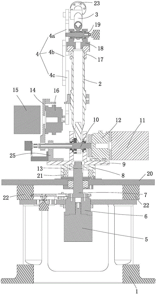
[0017] Below by embodiment and in conjunction with accompanying drawing, the present invention will be further described:

[0018] Such as figure 1 As shown, a desktop industrial robot consists of a base frame 1, a large arm 2, a small arm 3, a connecting rod 4, a first drive motor 5, a first reducer 6, a main drive connection plate 7, a large arm turntable 8, a large Arm base bracket 9, boom shaft 10, second drive motor 11, second reducer 12, spline 13, motor mounting plate 14, third drive motor 15, third reducer 16, boom flange 17 , forearm bracket 18, forearm shaft 19, work surface 20, plane bearing 21, table support block 22, mechanical claw motor installation flange 23, reducer installation connection plate 24, second drive motor support angle frame 25, etc. .

[0019] There is a cavity inside the base frame 1 , and a first driving motor 5 is vertically arranged in the cavity of the base frame 1 . After the first drive motor 5 is decelerated by the first reducer 6, the...


PUM


Abstract

The invention discloses a desktop industrial robot. According to the desktop industrial robot, a first driving motor is vertically arranged in a base frame, is reduced by the first reducer in speed and then drives a big-arm turntable and a big-arm base bracket to do 360-degree rotary motion through a main transmission connecting disc, a big-arm rotating shaft which is horizontally arranged is mounted on the big-arm base bracket, a second driving motor is arranged at one end of the big-arm rotating shaft, is reduced by the second reducer in speed and then drives a big arm and a motor mounted hanging plate to synchronously swing through the big-arm rotating shaft, the big arm and the motor mounted hanging plate are respectively extended upwardly and are parallel to each other, a third driving motor is horizontally arranged on the motor mounted hanging plat, is reduced by the third reducer in speed and then drives a connecting rod to swing, the upper end of the connecting rod is hinged to the rear end of a small arm, the front end of the small arm is used for mounting a mechanical claw, and the upper end of the big arm is hinged to a position, close to the rear end of the small arm, of the small arm. The desktop industrial robot has the advantages of simple structure, convenience in machining and higher flexibility.

Description

technical field [0001] The invention relates to the technical field of industrial robots, in particular to a desktop industrial robot. Background technique [0002] Industrial robot is an important automation equipment in modern manufacturing industry which integrates multi-disciplinary advanced technologies such as machinery, electronics, control, computer, sensor and artificial intelligence. Industrial robot products can be widely used in many fields such as automobile, metallurgy, electrical and electronics, chemical industry, engineering machinery, rail transit, low-voltage electrical appliances, electric power, IC equipment, military industry, tobacco, finance, medicine, printing and publishing, etc. In general, industrial robots can be used to replace jobs that are labor-intensive, harsh environments, highly repetitive, and difficult to guarantee manual technology and job safety. According to IFR, China will become the market with the largest demand for industrial rob...

Claims


Application Information

Patent Timeline
Patent Type & Authority Patents(China)
IPC IPC(8): B25J9/00B25J9/12
Inventor 邓效东吴良春
Owner 重庆市口天科技有限公司
Why Eureka
Try Eureka