Switch valve

A switching valve, valve body technology, applied in valve details, valve device, valve shell structure, etc., can solve problems such as screw off, poor quality of switching valve, uneven piston, etc.

Inactive Publication Date: 2014-12-24
ZHEJIANG DUNAN HETIAN METAL CO LTD
View PDF6 Cites 6 Cited by
  • Summary
  • Abstract
  • Description
  • Claims
  • Application Information

AI Technical Summary

Problems solved by technology

[0006] The purpose of the present invention is to provide a switching valve, which solves the problem that the screw falls off due to the uneven force on the piston and the end cover, resulting in poor quality of the switching valve.

Method used


Image

  • Switch valve
  • Switch valve
  • Switch valve

Examples


no. 1 approach

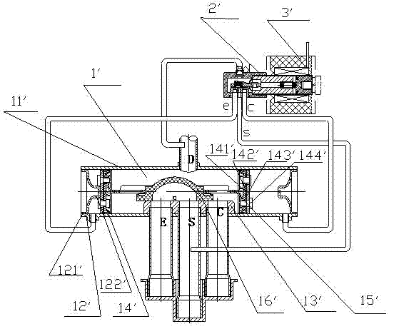
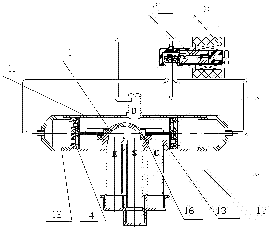
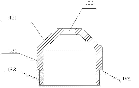
[0022] Such as figure 2 , 3 As shown, the switching valve includes the main valve 1, the pilot valve 2 and the coil 3. The electromagnetic force of the coil 3 acts on the pilot valve 2 to control the main valve 1 to realize the switching between cooling and heating of the air conditioner. The main valve 1 includes a hollow cylinder Shaped valve body 11, which blocks the end caps 12 at both ends of the valve body 11. The inner cavity of the valve body 11 is provided with a valve seat 13, two pistons 14 respectively placed on both sides of the valve seat 13, and two pistons connected to each other. The connecting rod 15 of 14 is fixedly arranged on the slider 16 in the middle of the connecting rod 15. The end cover 12 is in the shape of a hat, and the axis is successively provided with a cap top 121, a middle part 122 and a contact part 123. The cap top 121 or The middle part 122 is provided with a capillary hole 126 for installing a capillary. The main valve 1 and the pilot v...

no. 2 approach

[0027] Such as Figure 4 As shown, the difference between this embodiment and the first embodiment is that the outer diameters of the middle part 122 and the contact part 123 of the end cap 12 are equal, and the outer peripheral surface of the connection between the middle part 122 and the contact part 123 is provided with a convex ring 125, and the convex ring The outer diameter of 125 is greater than the outer diameter of the contact portion 123, so a step 124 is formed between the protruding ring 125 and the contact portion 123. The outer diameter of the protruding ring 125 is equal to the height of the outer peripheral surface of the valve body 11, forming a relatively smooth surface. The inner peripheral surfaces are in contact.

[0028] In this embodiment, the end cover 12 utilizes the protruding ring 125 on the outer peripheral surface at the junction of the middle part 122 and the contact part 123. When assembling, the contact part 123 of the end cover 12 is inserted ...


PUM


Abstract

The invention discloses a switch valve comprising a main valve, a pilot valve and a coil. The main valve comprises a hollow cylindrical valve body, end caps plugging two ends of the valve body and a piston sliding in an inner cavity of the valve body. The switch valve is characterized in that each end cap which is cap-shaped comprises a cap top, a middle portion and a contact portion arranged sequentially axially, a step is arranged between the middle portion and the contact portion, and the step is welded and fixed after butting against the end face of the valve body. The steps formed by difference in outer diameter of the middle portions and the contact portions of the end caps butt against the ends of the valve body, so that the end caps and the valve body are positioned, and the end caps and the valve body are convenient to assemble; meanwhile, during reversing of the switch valve, the end, namely a ring surface, of each contact portion butts against the piston; since smoothness of the ends of the contact portions is easy to control, finally caused inferior quality of the switch valve resulting from screw falling off caused by uneven stress of the piston due to the fact that small-diameter portions of the end caps are unsmooth in the prior art is prevented.

Description

technical field [0001] The invention belongs to the field of refrigeration control and relates to a switching valve. Background technique [0002] The switching valve is mainly composed of main valve 1', pilot valve 2' and coil 3'. During the control process, the reversing of the main valve 1' is realized through the joint action of the coil 3' and the pilot valve 2', so as to switch the flow direction of the refrigerant, so as to realize the switching between the cooling and heating working states of the heat pump air conditioner. Switching to achieve the purpose of cooling in summer and heating in winter. [0003] The switching valve main valve 1' is mainly composed of a valve body 11', an end cover 12' sealed and connected to both sides of the valve body 11', a valve seat 13' fixedly arranged in the inner cavity of the valve body 11', and Two pistons 14' on both sides of the valve seat 13', a connecting rod 15' connecting the two pistons 14', and a slider 16' fixedly ar...

Claims


Application Information

Patent Timeline
Patent Type & Authority Applications(China)
IPC IPC(8): F16K27/12
CPCF16K27/08
Inventor 金华海其他发明人请求不公开姓名
Owner ZHEJIANG DUNAN HETIAN METAL CO LTD
Why Eureka
Try Eureka