An electronic cigarette vaporizer heating device

A technology of electronic vaporizer and heating device, which is applied in the fields of tobacco, smoker’s supplies, applications, etc. It can solve the problems of fiber rope reducing the fluid guiding performance, not getting mixed output, difficult to diffuse smoke, etc., and achieves convenient assembly of fluid guiding Sufficient supply of medium and smoke liquid to improve the taste of smoke

Active Publication Date: 2017-10-03
SHENZHEN SMACO TECHNOLOGY LIMITED
View PDF7 Cites 0 Cited by
  • Summary
  • Abstract
  • Description
  • Claims
  • Application Information

AI Technical Summary

Problems solved by technology

[0005] (1) The heating wire needs to be evenly spirally wound on the fiber rope, which is difficult to assemble. Although the spiral winding method makes the heating wire fully contact with the fiber rope (or fluid-conducting cotton piece), the heating wire generally has a high temperature, so Once the fiber rope conducts insufficient fluid, it is easy to cause burning problems. Not only does the burnt fiber rope reduce the fluid conduction performance, but the burnt smell also brings the bad taste of the smoke;
[0006] (2) Although the airflow generated by the user's adsorption passes / passes through the heating wire and fiber rope (or fluid-conducting cotton sheet), due to the spiral winding structure of the heating wire, the smoke is difficult to diffuse and cannot be mixed with the airflow in time. output, so the amount of smoke output is small, the loss of smoke is large, the atomization efficiency is low, the suction required for smoking is high, and the experience is not good; and, because the airflow passes through the heating wire and the fiber rope, the atomization residue on the fiber rope Water and smoke liquid are easily output following the airflow, and then inhaled into the mouth

Method used


Image

  • An electronic cigarette vaporizer heating device
  • An electronic cigarette vaporizer heating device
  • An electronic cigarette vaporizer heating device

Examples


Embodiment Construction

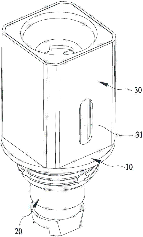
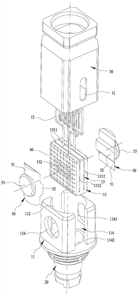
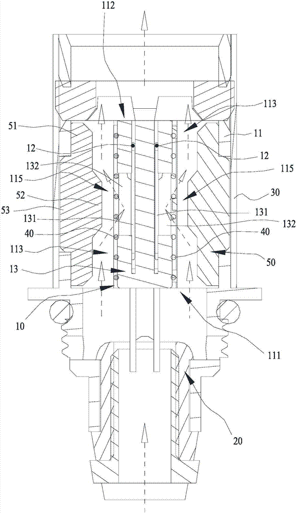
[0030] Such as Figure 1~3 The shown heating device of an electronic cigarette vaporizer includes a heating component 10 and a conductive component 20. The heating component 10 includes a fixing seat 11, a heating wire 12 and a liquid-conducting medium 13 for conducting smoke liquid. The fixing seat 11 is a medium The empty housing has an airflow inlet 111 and an airflow outlet 112 respectively located at opposite ends, and an airflow channel 113 for air flow is formed in the fixed seat 11 between the airflow inlet 111 and the airflow outlet 112, and the liquid guiding medium 13 is fixed on the fixed seat 11, the liquid guiding medium 13 is provided with an embedded groove 131, the heating wire 12 is embedded in the embedded groove 131 and is attached to the inner wall of the embedded groove 131, and at least one groove wall of the embedded groove 131 is provided with a hole that runs through the groove wall. The smoke port 132, the embedded groove 131 communicates with the fi...


PUM


Abstract

The invention discloses a heating device for an electronic smoke atomizer, which includes a heating component and a conductive component. The heating component includes a fixing seat, a heating wire and a liquid-conducting medium. Inlet and air outlet, the fixed seat between the air inlet and the air outlet forms an air flow channel for the flow of air, and the liquid guiding medium is fixed in the fixing seat, and the liquid guiding medium is provided with an embedded groove, and the heating wire is embedded in the embedded groove and be attached to the inner wall of the caulking groove, at least one of the groove walls of the caulking groove is provided with a smoke port penetrating the groove wall, and the caulking groove communicates with the inside of the fixed seat through the smoke port, and at least one of the groove walls of the caulking groove is also provided with a through hole The groove wall is also a hole for the heating wire to pass through; the conductive component is installed on the fixing seat and electrically connected with the heating wire. The invention can efficiently generate smoke, fully diffuse the smoke, and output it in time, and has a good smoke taste, avoiding burnt taste, atomized residual water or smoke liquid being sucked into people's mouth.

Description

technical field [0001] The invention relates to parts of electronic cigarettes, in particular to a heating component of an electronic cigarette atomizer. Background technique [0002] Electronic cigarettes, also known as atomizers, electronic cigarettes, and virtual cigarettes, are mainly used to quit smoking and replace cigarettes. It has the appearance and taste similar to cigarettes. [0003] The current electronic cigarette is generally composed of a mouthpiece assembly, an atomizer and a liquid storage assembly, and the atomizer includes a heating assembly and a conductive assembly. The heating component generally includes a heating wire and a fiber rope (or a fluid-guiding cotton piece), the heating wire is spirally wound on the fiber rope (or a fluid-guiding cotton piece), and the fiber rope is used to guide the smoke liquid in the liquid storage component. When in use, the heating wire is energized through the conductive component, and the heating wire of the heati...

Claims


Application Information

Patent Timeline
Patent Type & Authority Patents(China)
IPC IPC(8): A24F47/00A24F40/10A24F40/46A24F40/485
CPCA24F40/485A24F40/46A24F40/10
Inventor 朱晓春
Owner SHENZHEN SMACO TECHNOLOGY LIMITED
Why Eureka
Try Eureka