An electromechanical dual-purpose green grass braiding forming device

A forming device and dual-purpose technology, applied in the field of grass braid forming device, can solve the problems of low manual efficiency, irregular grass braids, etc., and achieve the effects of improving efficiency, low power consumption, and reducing pasture mildew.

CN104396464BInactive Publication Date: 2016-04-27CHINA AGRI UNIV
5 Cites 0 Cited by

Patent Information

Authority / Receiving Office
CN · China
Patent Type
Patents(China)
Current Assignee / Owner
Publication Date
2016-04-27
Estimated Expiration
Not applicable · inactive patent

Smart Images

  • Figure 1
    Figure 1
  • Figure 2
    Figure 2
  • Figure 3
    Figure 3
Patent Text Reader

Abstract

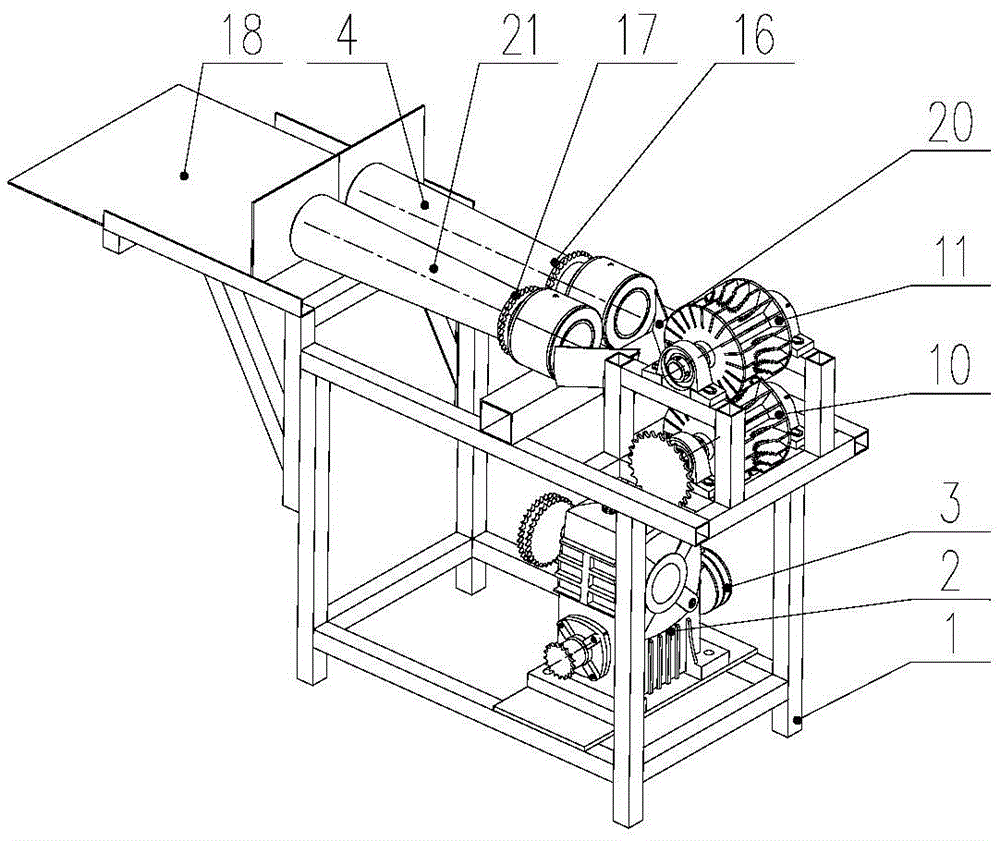
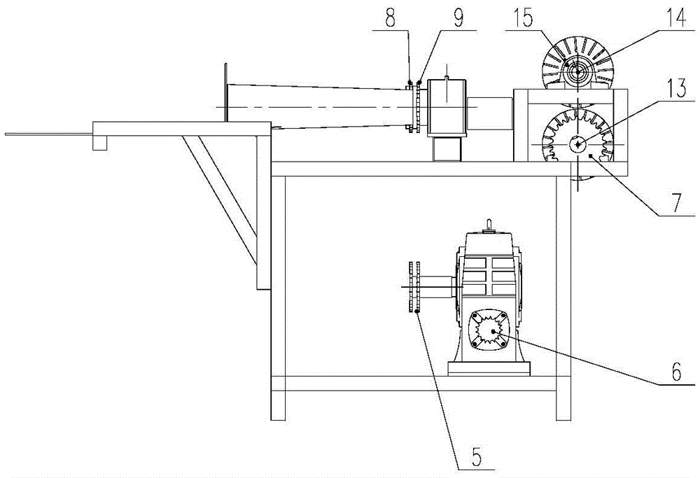
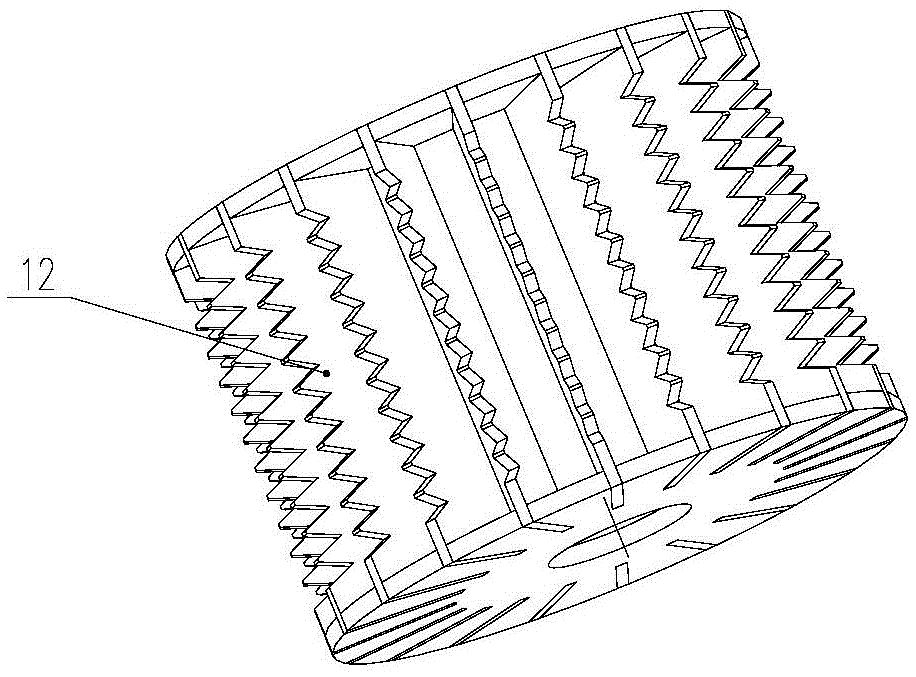
The invention belongs to the field of forage grass machining machines, and particularly relates to an electromechanical dual-purpose green grass braiding-molding device. The molding device comprises a frame (1), a gearbox (2), a left molding drum (4), a right molding drum (21), a traction grass roller (10), a driven grass roller (11), a left chain wheel ring (8), a right chain wheel ring (9), a feeding support plate (18) and a guide plate (20), wherein the traction grass roller (10) and the driven grass roller (11) are wire coils of which the middles are provided with shaft holes into which a driving shaft (13) and a driven shaft (14) are inserted respectively and both sides are provided with circular disks; tooth-shaped clamping sheets (12) are radially and uniformly distributed on the groove parts in the middles of the traction grass roller (10) and the driven grass roller (11). The electromechanical dual-purpose green grass braiding-molding device is used for braiding and molding harvested fresh grass, is light and simple in structure, can work under the output power of a motor or a small four-wheel tractor, is low in power consumption, has a good field operation effect, is low in labor intensity, and is convenient for herdsmen to machine and transport forage grass conveniently in time after harvesting.
Need to check novelty before this filing date? Find Prior Art

Description

technical field

[0001] The invention belongs to the field of forage processing machinery, and in particular relates to an electromechanical dual-purpose green grass braiding forming device. Background technique

[0002] Grass is the basis for the development of livestock production, especially the production of grass-fed livestock. The forage harvest season in my country mostly coincides with the rainy season. After harvesting the forage in rainy areas, artificial mechanical drying can solve the problem of forage drying in large farms. However, in self-sufficient pastoral areas, especially the vast pastoral areas of the Qinghai-Tibet Plateau, large-scale drying equipment does not perform well. space.

[0003] Field investigations have shown that making grass braids and then using "hay racks" to ventilate and dry grass is a form of forage storage used by small-scale farmers and herdsmen in many areas of the Qinghai-Tibet Plateau. Yet the preparation of grass braids at presen...

Examples

Embodiment Construction

[0040] The specific implementation manners of the present invention will be further described in detail below in conjunction with the accompanying drawings.

[0041] like figure 1 , 2 As shown, the electromechanical grass braiding forming device of the present invention includes a left forming drum 4 , a right forming drum 21 , a traction grass roller 10 and a driven grass roller 11 .

[0042] The molding device also includes a frame 1 , a gearbox 2 , a left sprocket rim 8 , a right sprocket rim 9 , a feeding pallet 18 and a guide plate 20 .

[0043] The structural forms and external dimensions of the left molding drum 4 and the right molding drum 21 are the same.

[0044] like Figure 4 As shown, the left molding drum 4 and the right molding drum 21 are cone drums with large feed end and small discharge end, and a pair of lifting plates 19 are installed inside.

[0045] The left forming drum 4 is fixedly connected to the left sprocket ring 8 through the left flange 16 ; t...