Mobile connecting rod mechanism

A connecting rod mechanism and mobile technology, applied in the field of robotics, can solve the problems of low stiffness, small working space, and large torque required, and achieve the effects of good dynamic performance, lower center of gravity, and reduced active torque

Inactive Publication Date: 2015-04-29
GUANGXI UNIV
View PDF5 Cites 0 Cited by
  • Summary
  • Abstract
  • Description
  • Claims
  • Application Information

AI Technical Summary

Problems solved by technology

[0003] The technical problem to be solved by the present invention is to provide a mobile link mechanism to solve the shortcomings of traditional serial robots about large torque required, low rigidity and small working space

Method used


Image

  • Mobile connecting rod mechanism
  • Mobile connecting rod mechanism
  • Mobile connecting rod mechanism

Examples


Embodiment Construction

[0022] The technical solutions of the present invention will be further described below in conjunction with the accompanying drawings and embodiments.

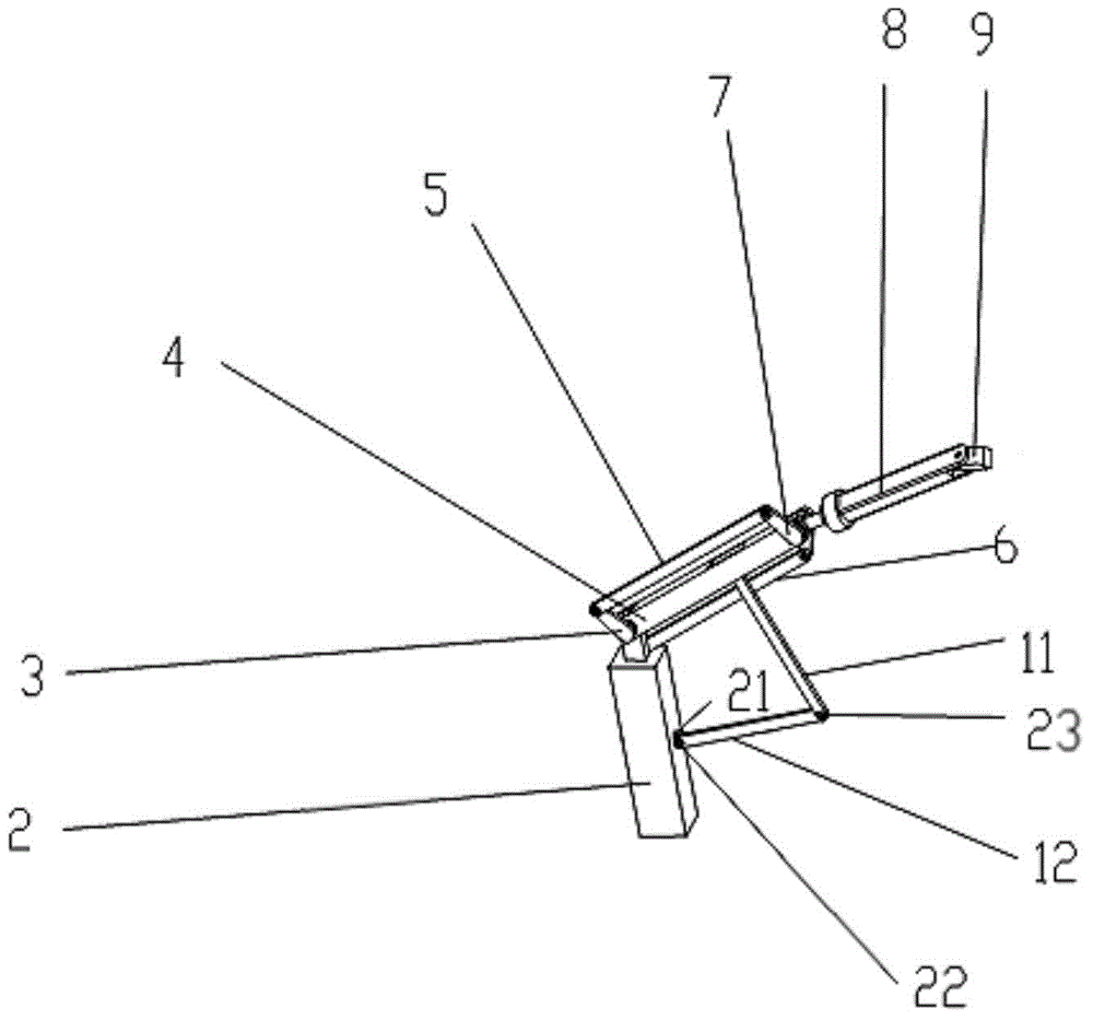
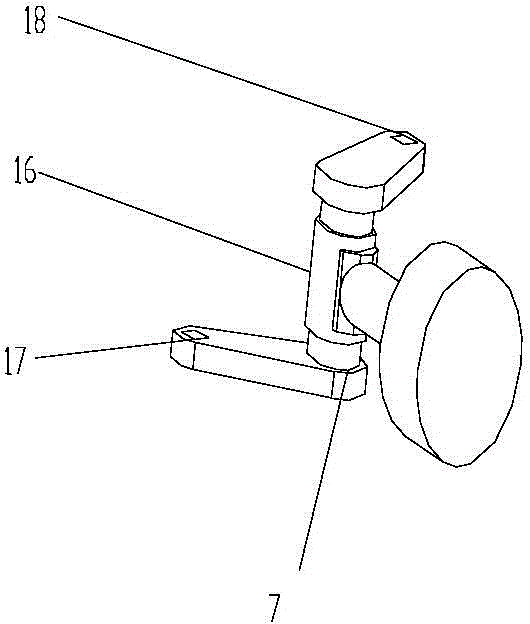
[0023] Such as Figure 1-Figure 6 As shown, a movable link mechanism includes a column 2, a main arm 4, a first rocker arm 3, a second rocker arm 7, a first link 5, a second link 6, a third link 8, a first link Four connecting rods 9 , connecting block 21 , fifth connecting rod 12 and sixth connecting rod 11 .

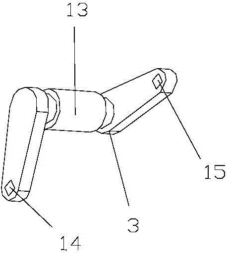
[0024] The bottom end of the column 2 is used to connect the traveling mechanism 1, and the top end of the column 2 is respectively connected to the first connection end of the main arm 4 and the first connection end of the first rocker arm 3 through the first rotating pair 13. The first rocker arm 3 The second connecting end is connected with one end of the first connecting rod 5 through the second rotating pair 14, and the other end of the first connecting rod 5 is connected with the second connecting end of the sec...


PUM


Abstract

The invention relates to a mobile connecting rod mechanism. A vertical column is connected with one end of a main arm and a first connecting end of a first rocker arm; a second connecting end of the first rocker arm is connected with one end of a first connecting rod; the other end of the first connecting rod is connected with a second connecting end of a second rocker arm; a first connecting end of the second rocker arm is connected with the other end of the main arm; a third connecting end of the second rocker arm is connected with one end of a second connecting rod; the other end of the second connecting rod is connected with a third connecting end of the first rocker arm; one end of a third connecting rod is connected with a fourth connecting end of the second rocker arm; the other end of the third connecting rod is connected with a fourth connecting rod; one end of a connection block is connected with the vertical column through a fixing pair; the other end of the connection block is connected with one end of a fifth connecting rod; the other end of the fifth connecting rod is connected with one end of a sixth connecting rod; the other end of the sixth connecting rod is connected with the middle part of the main arm. The mobile connecting rod mechanism has the advantages of large working space, high rigidity, strong bearing capacity and high executing precision.

Description

technical field [0001] The invention relates to the field of robots, in particular to a movable link mechanism. Background technique [0002] Compared with the traditional serial robot, the parallel robot has no cumulative error, high precision, compact structure, large bearing capacity, high rigidity and small inertia of the actuator. and other characteristics, the driving device can be placed on the fixed platform or close to the fixed platform, so that the moving part is light in weight, high in speed, and good in dynamic response; but the obvious disadvantages of parallel robots are small working space and complex structure. Existing manipulators with partial closed chains such as MOTOMAN-K10 in engineering do not solve the problems of industrial robots. Contents of the invention [0003] The technical problem to be solved by the present invention is to provide a movable link mechanism, which solves the shortcomings of traditional tandem robots about large torque requ...

Claims


Application Information

Patent Timeline
Patent Type & Authority Applications(China)
IPC IPC(8): B25J9/00
Inventor 蔡敢为范雨张林李智杰张永文李荣康朱凯君王龙王小纯李岩舟杨旭娟
Owner GUANGXI UNIV
Why Eureka
Try Eureka