

Valve block with valve arrangement
A technology of valve device and valve group, which is applied in the direction of fluid pressure actuation device, transportation and packaging, servo motor components, etc., which can solve the problems of high structural space requirements and achieve the effect of reducing costs
- Summary
- Abstract
- Description
- Claims
- Application Information
AI Technical Summary
Problems solved by technology
Method used
Image

Examples
Embodiment Construction
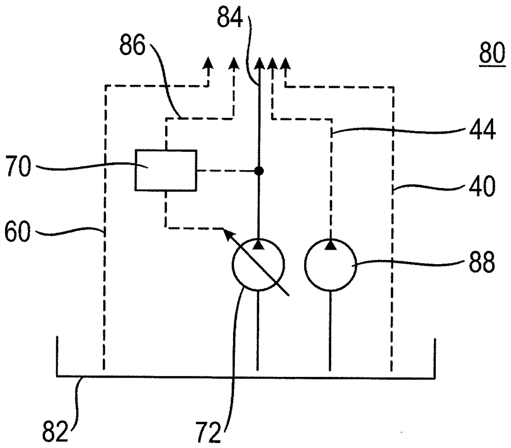
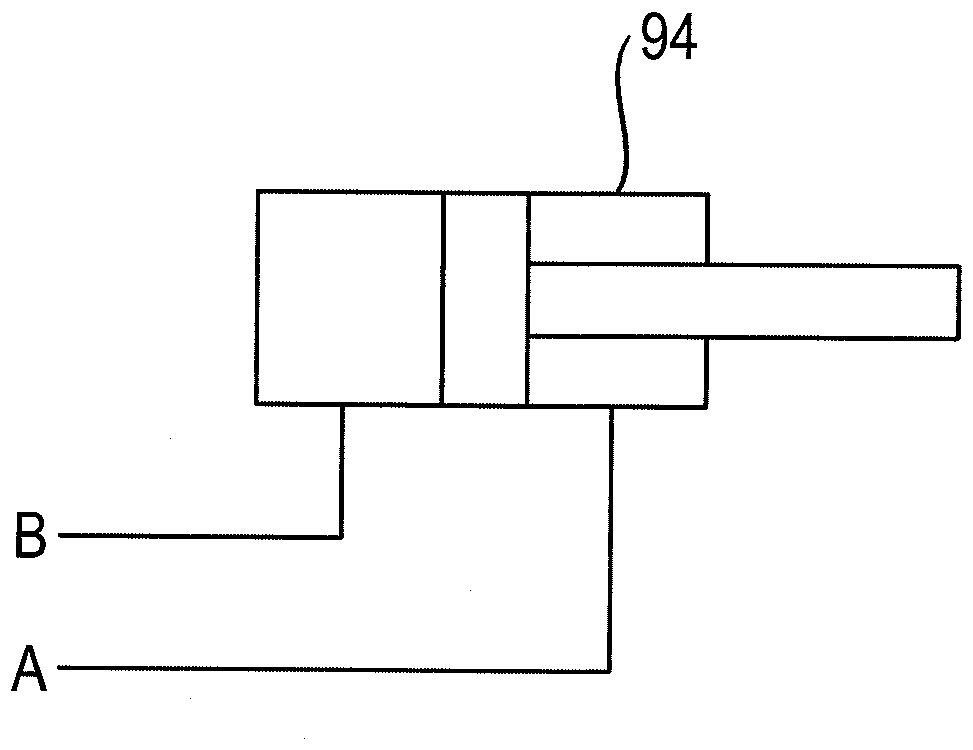
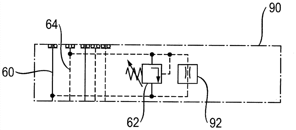
[0041] according to figure 1 A valve arrangement 1 according to the invention in the form of a valve block 2 is shown. It has a plurality of control valve disks 10 to 12 and a pressure limiting valve disk 14 . The control valve disks 4 to 8 in this case form a first group part 16 and the control valve disks 10 and 12 form a second group part 18 . A consumer can be connected to the respective control valve disk 4 to 12 via the working ports A and B. To control the speed and direction of the respective consumer, the respective control valve disk 4 to 12 has a control valve 20 , wherein only the control valve 20 of the control valve disk 4 is shown with reference numerals for the sake of overview.
[0042] Since the control valve disks 4 to 12 are designed identically, the structure of the corresponding control valve disks 4 to 12 will be explained in detail with reference to the control valve disk 4 . The working port A of the control valve disk 4 is connected to the control ...
PUM
 Abstract
Description
Claims
Application Information