Automatic transfer switch transmission mechanism

A technology of automatic transfer switch and transmission mechanism, which is applied to the power device, electric switch, contact operating mechanism and other directions inside the switch, which can solve the problems of sticking of the push rod, complicated installation and low use efficiency, and improve the reliability of operation. , Improve work efficiency, simple and convenient structure

Active Publication Date: 2015-05-27
ZHEJIANG CHINT ELECTRIC CO LTD
View PDF6 Cites 6 Cited by
  • Summary
  • Abstract
  • Description
  • Claims
  • Application Information

AI Technical Summary

Problems solved by technology

When the automatic transfer switch is manually operated, since the motor part of the transmission mechanism has no clutch structure, when the handle is turned, the output shaft of the motor will be driven to rotate together, resulting in a large manual operation force and reducing the operational stability of the transmission mechanism.
The transmission mechanism of some existing automatic transfer switches is also equipped with a clutch structure. In this clutch structure, a solenoid valve is used to drive the push rod to lock, so that there are many parts in the clutch structure and the installation is complicated and the efficiency is low. At the same time, the push rod is in the process of action. There is a problem of jamming, which reduces the reliability of the transmission mechanism
Moreover, the action of the existing solenoid valve is controlled and driven by the controller, so there is a hidden danger of malfunction

Method used


Image

  • Automatic transfer switch transmission mechanism
  • Automatic transfer switch transmission mechanism
  • Automatic transfer switch transmission mechanism

Examples


Embodiment Construction

[0024] The following is attached Figures 1 to 8 The embodiment of the present invention is given to further illustrate the specific implementation of the transmission mechanism of the automatic transfer switch of the present invention. The transmission mechanism of the automatic transfer switch of the present invention is not limited to the description of the following embodiments.

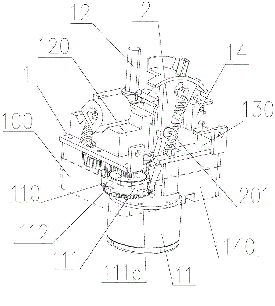
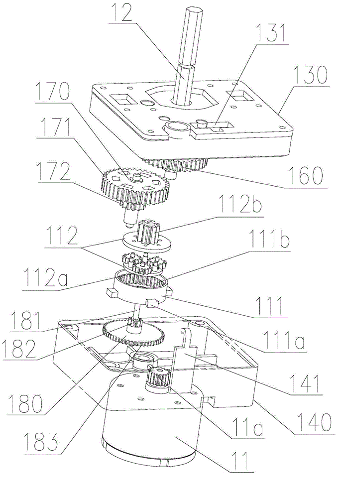
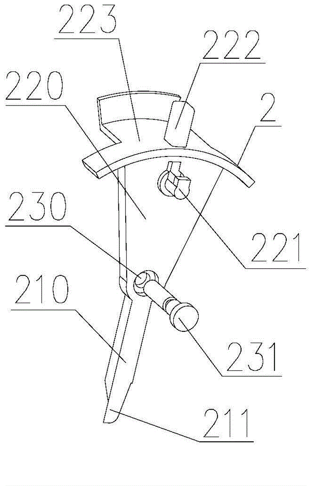
[0025] The automatic transfer switch of the present invention comprises the transmission mechanism 1 fixedly installed on the base plate 300, the executive switch 3 and the controller 15, such as Figure 8 As shown, execution switches 3 are respectively installed on both sides of the transmission mechanism 1 so that the transmission mechanism 1 can be mechanically coupled with two execution switches 3 nearby. The execution switch 3 includes a push rod 301 that can drive the execution switch 3 to act. The above-mentioned push rod is connected with the rocker arm 12c of the transmission mechanism ...


PUM


Abstract

The invention discloses an automatic transfer switch transmission mechanism. The transmission mechanism comprises a motor, an output shaft and a reduction gearbox, wherein a planetary gear set for clutching the motor and the output shaft is arranged inside the reduction gearbox; the planetary gear set comprises a planetary gear ring and a planet carrier which are mounted in a relative rotating manner; the planet carrier is respectively in transmission connection with the motor and the output shaft; the planetary gear ring sleeves the outer part of the planet carrier; a lug boss (111a) is further arranged on the outer wall of the planetary gear ring; the transmission mechanism further comprises a locking arm which can swing relative to the reduction gearbox; the end part of the locking arm is arranged in the reduction gearbox and corresponding to the planetary gear ring; under the automatic state, the end part of the locking arm can interfere with the lug boss to stop rotation of the planetary gear ring, so as to enable the motor to drive the output shaft to rotate. The automatic transfer switch transmission mechanism provided by the invention is stable in clutch structure, simple and convenient in operation process, and simple in mechanical structure.

Description

technical field [0001] The invention relates to the field of low-voltage electrical appliances, in particular to an automatic transfer switch transmission mechanism. Background technique [0002] At present, the automatic transfer switch is composed of an executive switch, a transmission mechanism and a controller. When the automatic transfer switch is manually operated, since the motor part of the transmission mechanism has no clutch structure, the output shaft of the motor will be driven to rotate when the handle is turned, resulting in a large manual operation force and reducing the operational stability of the transmission mechanism. The transmission mechanism of some existing automatic transfer switches is also equipped with a clutch structure. In this clutch structure, a solenoid valve is used to drive the push rod to lock, so that there are many parts in the clutch structure and the installation is complicated and the efficiency is low. At the same time, the push rod ...

Claims


Application Information

Patent Timeline
Patent Type & Authority Applications(China)
IPC IPC(8): H01H3/26H01H3/58
CPCH01H3/26H01H3/58
Inventor 黄甫
Owner ZHEJIANG CHINT ELECTRIC CO LTD
Why Eureka
Try Eureka