Flaw detecting device for detecting bottom cracks or defects of steel rail

A technology for flaw detection devices and cracks, which is applied in the direction of measuring devices, instruments, scientific instruments, etc., can solve the problems that the pattern recognition method cannot detect internal damage, cannot meet the needs of rail flaw detection, and the ray method has radiation, etc., to achieve strong adaptability and high reliability performance, high detection efficiency

Inactive Publication Date: 2015-06-10
BEIJING JIAOTONG UNIV
View PDF7 Cites 2 Cited by
  • Summary
  • Abstract
  • Description
  • Claims
  • Application Information

AI Technical Summary

Problems solved by technology

However, the existing ultrasonic flaw detection technology is inefficient and cannot meet the flaw detection needs of steel rails
In addition, other rail flaw detection methods in the prior art have certain defects, such as ray method has radiation, magnetic flux leakage method and infiltration method both have high environmental requirements, pattern recognition method cannot detect internal damage, acoustic, magnetostriction and longitudinal ultrasonic conduction The wave method is not sensitive to shallow surface fish scales, so these methods have relatively large defects

Method used


Image

  • Flaw detecting device for detecting bottom cracks or defects of steel rail
  • Flaw detecting device for detecting bottom cracks or defects of steel rail
  • Flaw detecting device for detecting bottom cracks or defects of steel rail

Examples


Embodiment Construction

[0037] The content of the invention of the present invention will be further described below in conjunction with the accompanying drawings and embodiments.

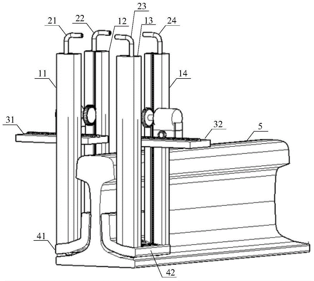
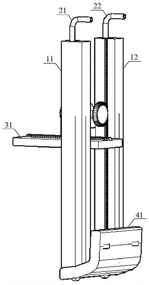
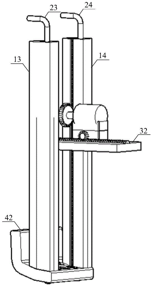
[0038] Such as figure 1 As shown, the flaw detection device for detecting cracks or defects at the bottom of the rail provided in this embodiment includes a first support column 11, a second support column 12, a third support column 13, a fourth support column 14, a first air duct 21, The second air duct 22 , the third air duct 23 , the fourth air duct 24 , the first transmission mechanism 31 , the second transmission mechanism 32 , the first bottom plate 41 and the second bottom plate 42 .

[0039] A through hole (not shown in the figure) is provided inside the first support column 11 , the second support column 12 , the third support column 13 and the fourth support column 14 . Both the first bottom plate 41 and the second bottom plate 42 are L-shaped, and both the first bottom plate 41 and the second bottom plate 42 a...


PUM


Abstract

The invention discloses a flaw detecting device for detecting bottom cracks or defects of a steel rail. The flaw detecting device for detecting the bottom cracks or defects of the steel rail comprises a first support column (11), a second support column (12), a third support column (13), a fourth support column (14), a first transmission mechanism (31), a second transmission mechanism (32), a first bottom plate (41) and a second bottom plate (42). Both the first bottom plate (41) and the second bottom plate (42) are in an L shape; the first support column (11) and the second support column (12) are arranged on both sides of the first transmission mechanism (31), and the bottom ends of the first support column (11) and the second support column (12) are fixedly connected with the upper end surface of the first bottom plate (41); the third support column (13) and the fourth support column (14) are arranged on both sides of the second transmission mechanism (32), and the bottom ends of the third support column (13) and the fourth support column (14) are fixedly connected with the upper end surface of the second bottom plate (42); the upper end surface of the first bottom plate (41) is provided with a plurality of pits (411), and the center of every pit (411) is provided with a stand column (412). The flaw detecting device for detecting the bottom cracks or defects of the steel rail can detect internal flaws in the middle of the bottom of the steel rail and achieve high sensitivity.

Description

technical field [0001] The invention relates to the technical field of rail flaw detection, in particular to a flaw detection device for detecting cracks or defects at the bottom of rails. Background technique [0002] Rail is an important infrastructure of rail transit and the most important factor to ensure driving safety. Rail flaw detection is an important means to ensure that the rail is in a safe state. In the practice of flaw detection, it is difficult to find the defects on the two extended sides of the bottom of the rail, and such defects can easily develop into broken rails. Especially in winter in the north, the steel rail will generate huge tensile stress, which will accelerate the development of this defect. [0003] In the prior art, ultrasonic detection technology is commonly used for rail flaw detection. Ultrasonic detection technology can detect larger depths, but it can only detect cracks in the projected area from the top of the rail to the bottom of th...

Claims


Application Information

Patent Timeline
Patent Type & Authority Applications(China)
IPC IPC(8): G01N33/00
Inventor 刘泽罗金旺赖福智高伟刘丰周锦洪
Owner BEIJING JIAOTONG UNIV
Why Eureka
Try Eureka