Rotor expander

A rotor expansion and male rotor technology, applied in the field of rotor expanders, can solve the problems of shortening the service life of the blades, increasing the use cost, reducing the work efficiency, etc., and achieve the effect of improving the overall efficiency, increasing the efficiency, and reducing the use cost

Inactive Publication Date: 2015-08-26
张茂岽
View PDF2 Cites 11 Cited by
  • Summary
  • Abstract
  • Description
  • Claims
  • Application Information

AI Technical Summary

Problems solved by technology

The blades and the cylinder are kept in close contact under the action of the spring, and there is sliding friction between the blades and the cylinder during the rotation of the rotor. The tight contact makes the compressor less efficient, and the compression is loose and e...

Method used


Image

  • Rotor expander
  • Rotor expander
  • Rotor expander

Examples


Embodiment 1

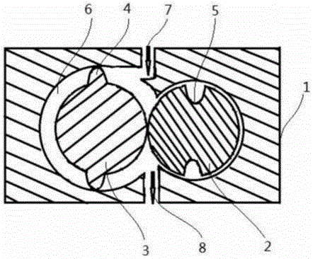
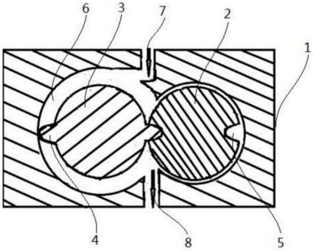
[0035] Such as figure 1 and image 3 As shown, the present invention discloses a rotor expander, which includes a cylinder body 1 , a female rotor 2 and a male rotor 3 inside the cylinder body 1 . The male rotor 3 and the female rotor 2 are cylinders with tangential outer diameters and the same diameter. The cylinder body 1 is provided with a synchronous gear that drives the male rotor 3 and the female rotor 2 to rotate synchronously and reversely. The synchronous gear is an existing A common structure in the technology will not be repeated here. The male rotor 3 is provided with protruding vanes 4 extending radially outward from its outer circumference, and the female rotor 2 is provided with grooves 5 that cooperate with the protruding vanes 4 on the male rotor 3 When the male rotor 3 and the female rotor 2 rotate synchronously in reverse to the meshing position, the protruding blades 4 fit into the grooves 5 . An annular gas channel 6 is provided inside the cylinder body...

Embodiment 2

[0041] Such as Figure 4 and Figure 5 As shown, the principle and structure of this embodiment and Embodiment 1 are basically the same, the difference is that there are two male rotors, and the two male rotors are symmetrically arranged on both sides of the female rotor, and a total of Two grooves corresponding to the male rotor. Said gas channel surrounds the outer surface of each male rotor successively from the air inlet to the air outlet.

Embodiment 3

[0043] Such as Figure 6 and Figure 7 , the principle and structure of this embodiment and Embodiment 1 are basically the same, the difference is that there are four male rotors, and the four male rotors are evenly distributed along the circumferential direction of the female rotor, and there are four The corresponding groove of the male rotor. When the four male rotors are in a series structure, the gas channel surrounds the outer surface of each male rotor in turn from the air inlet to the air outlet. The four male rotors can also be connected in parallel, and the principle is the same.

[0044] In addition, it can also be designed as a structure of 6 male rotors and 1 female rotor, 6 male rotors are evenly distributed along the circumference of the female rotor, and 6 grooves are evenly distributed on the female rotor to match the blades of each male rotor. Blade and groove also can be other shapes such as rectangle.

[0045] The present invention does not have sliding...


PUM


Abstract

The invention discloses a rotor expander, and relates to the technical field of rotating piston type machines or engines. The rotor expander comprises a cylinder, a female rotor in the cylinder, and at least one male rotor, wherein two vertical grooves are formed in a projected blade, and extend to the inner wall direction of the cylinder; springs and cuboid air seals are arranged in the two vertical grooves; one ends of the springs are fixedly connected with the vertical grooves, and the other ends of the springs are connected with the cuboid air seals in the vertical grooves; a machine oil channel parallel to a main shaft and an inverted T-shaped machine oil outlet communicated with the machine oil channel are arranged between the two vertical grooves; an inverted T-shaped oil ring matched with the inverted T-shaped machine oil outlet is arranged in the inverted T-shaped machine oil outlet; and the inverted T-shaped oil ring extends to the inner wall of the cylinder. The expander has the characteristics of high mechanical efficiency, easy processing, no wearable parts, long service life and low operation and maintenance costs.

Description

technical field [0001] The invention relates to the technical field of rotary piston machines or engines, in particular to a rotor expander with high mechanical efficiency, easy processing, no wearing parts, long service life and low operation and maintenance costs. Background technique [0002] In recent years, as the greenhouse effect has become more and more serious and the air quality has deteriorated, energy conservation and emission reduction has become the goal that the whole country is striving for. In order to improve the efficiency of refrigeration and heat pump systems, in recent years, people have made a lot of articles on the design of cycle principles, high-efficiency compression, throttling mechanisms, and heat exchangers, but the expander is still a weak link. Turbo expander and piston expander are the key equipment to obtain low temperature. With the continuous expansion of the application range of expanders and the continuous improvement of people's applic...

Claims


Application Information

Patent Timeline
IPC IPC(8): F01C1/28F01C21/08F01C19/00F01C21/04F03C2/24F04C18/28F04C27/00F04C29/02
CPCF01C1/28F01C19/005F01C21/04F01C21/08F03C2/24F04C18/28F04C27/004F04C29/025
Inventor 张茂岽
Owner 张茂岽
Why Eureka
Try Eureka