
A door shaft mechanism
A door shaft and box door technology, which is applied to door/window accessories, building structures, hinged panels, etc., can solve problems such as reducing customer satisfaction with products and affecting product appearance, and achieve improved product appearance, small gaps, and Enhanced sealing effect
- Summary
- Abstract
- Description
- Claims
- Application Information
AI Technical Summary
Problems solved by technology
Method used
Image

Examples
Embodiment Construction
[0017] The technical solutions claimed in the present invention will be further described in detail in conjunction with the accompanying drawings and specific embodiments.
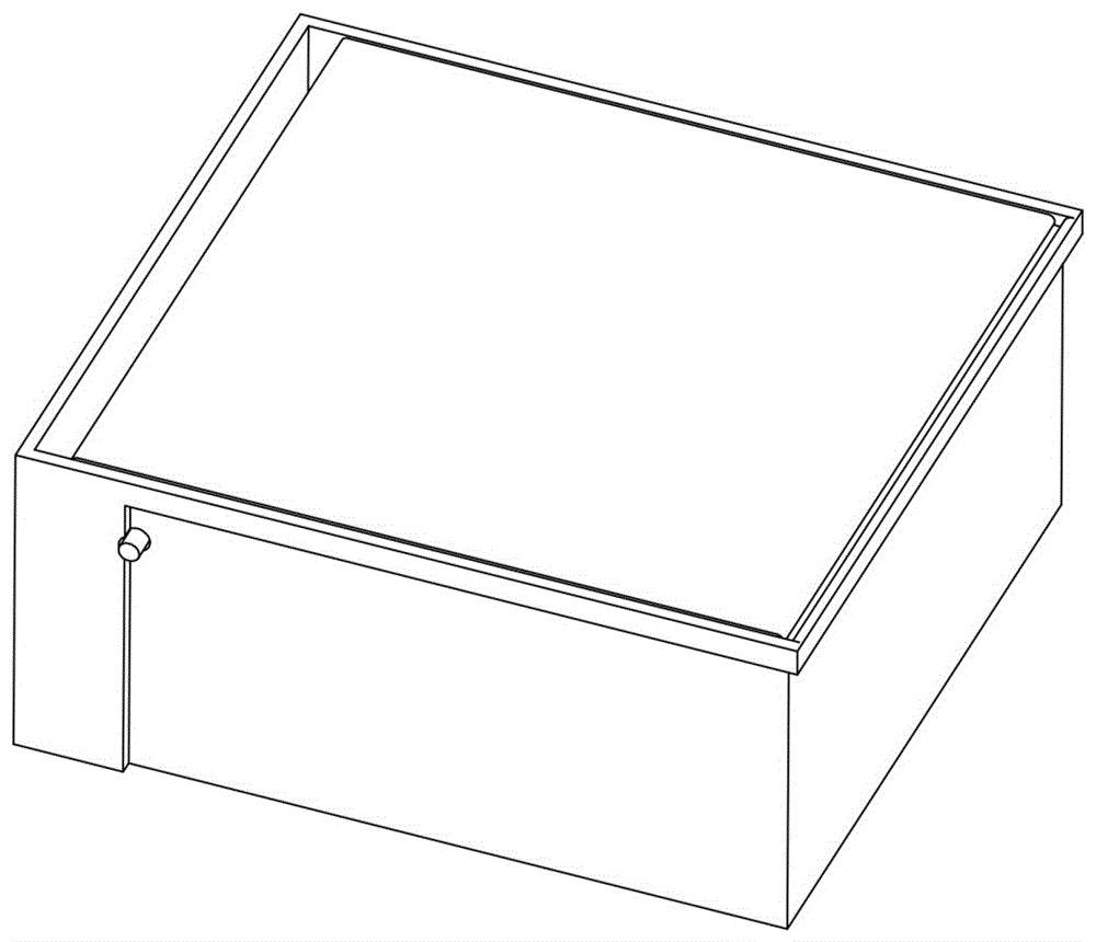
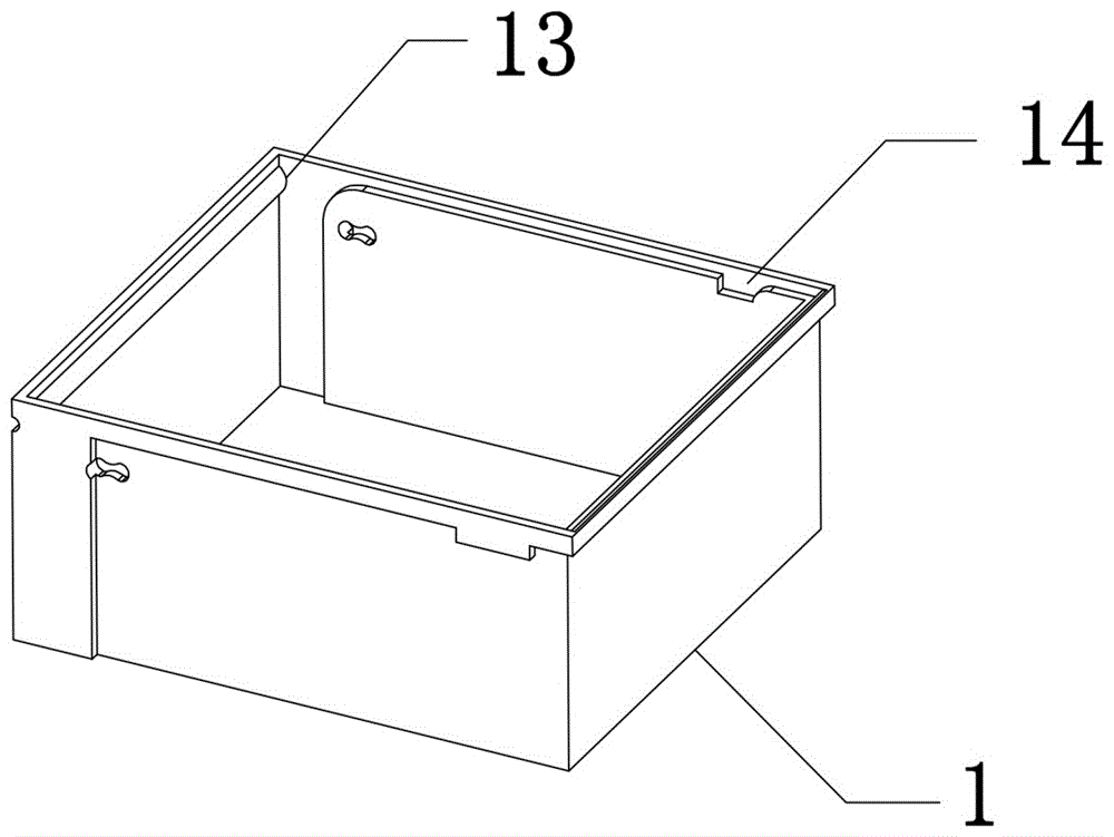
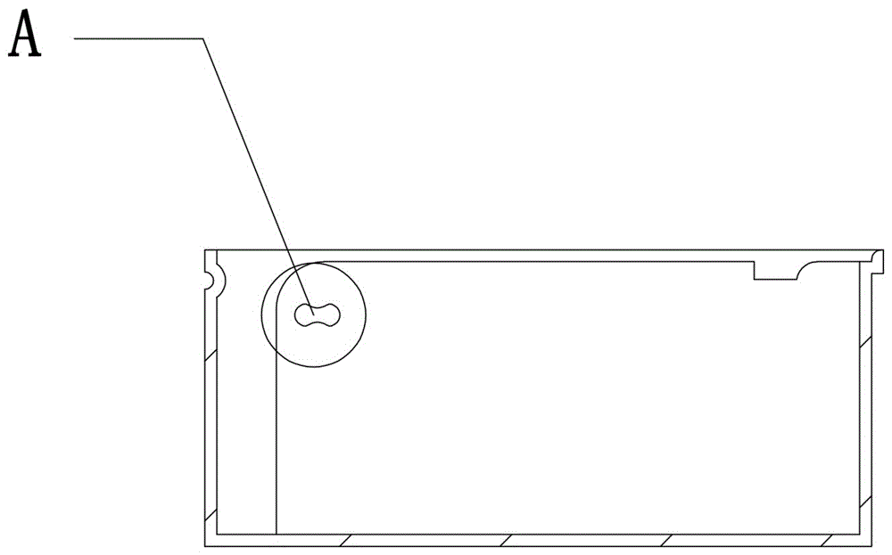
[0018] See attached Figure 2-4 As shown, the door shaft mechanism in this embodiment includes a box body 1 and a box door 2 , the box door 2 is rotationally connected with the box body 1 , and the box door 2 is opened or closed by turning the box door 2 . Wherein, the box door 2 is formed with a rotating shaft 21 near its side, and the box body 1 is provided with two rotating shaft holes 11 matched with the rotating shaft 21 at the corresponding position, through which the rotating shaft 21 and the rotating shaft hole 11 The cooperation will make the box door 2 rotate and be connected to the box body 1, and the two shaft holes 11 are arranged in the horizontal direction, wherein one shaft hole 11 corresponds to the open state of the box door 2, and the other shaft hole 11 corresponds to the closed state o...
PUM
 Abstract
Description
Claims
Application Information