Movable discharge device of belt conveyor

A technology of belt conveyor and unloading device, which is applied in the direction of conveyor objects, transportation and packaging, etc. It can solve the problems of increasing the height of the transfer station, reducing the service life, and limited upper and lower space, so as to simplify the process layout and save vertical space , the effect of reducing the upfront cost

Active Publication Date: 2015-10-07
NORTHERN HEAVY IND GRP CO LTD
View PDF10 Cites 0 Cited by
  • Summary
  • Abstract
  • Description
  • Claims
  • Application Information

AI Technical Summary

Problems solved by technology

When the two landing points of the downstream belt conveyor are far away and the upper and lower spaces are limited, the design method of adding three-way slides obviously cannot meet the process requirements.
Moreover, in the form of a three-way chute, the material flow impacts the inner flap of the three-way chute for a long time, causing the flap to deform, which in turn causes damage to the electric push rod connected to it, and the shaft of the flap is broken, which reduces the life of the product. It is often shut down for maintenance, which affects the normal production of users
If it is designed as a telescopic head belt conveyor, it is necessary to change the original process layout and increase the height of the transfer station, which greatly increases the cost
Moreover, the above two methods can only unload at a single point, and cannot unload at two unloading points at the same time, and cannot divide the flow proportionally; they cannot monitor the change of the material level in real time; when to change the position of the unloading point, manual judgment is required, and the error Great, increased labor costs

Method used


Image

  • Movable discharge device of belt conveyor
  • Movable discharge device of belt conveyor

Examples


Embodiment Construction

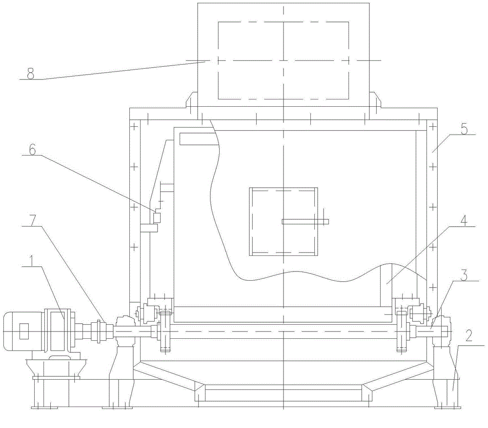
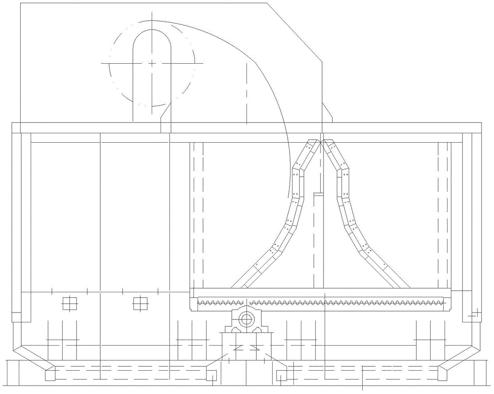
[0012] Referring to the accompanying drawings, a mobile unloading device for a belt conveyor includes a driving device 1, a base 2, a transmission device 3, a reversing baffle 4, a funnel body 5, a travel switch 6, a coupling 7, a head guard The cover 8 connects the driving device 1 and the base 2 with threads, the transmission device 3 runs through the funnel body 5, and is threaded with the base 2, and the shaft extension at one end of the transmission device 3 is connected with the drive device 1 by a coupling 7; the funnel body 5 and the The base 2 is threaded; the reversing baffle 4 is placed inside the funnel body 5, and the transmission device 3 is engaged with the chain on the reversing baffle 4, and the head shield 8 and the funnel body 5 are connected by flanges; Travel switches 6 are installed at both ends of the belt conveyor mobile unloading device.

[0013] The working principle of the mobile unloading device of the belt conveyor is that the driving device 1 is u...


PUM


Abstract

A movable discharge device of a belt conveyor is applied to the technical field of power, ports, metallurgy and mines and comprises a driving device, a base, a transmission device, a reversing baffle, a funnel, travel switches, a coupler and a head protection cover. The driving device is connected with the base through a thread. The transmission device penetrates through the funnel and is connected with the base through a thread. A shaft extension at one end of the transmission device is connected with the driving device through the coupler. The funnel is connected with the base through a thread. The reversing baffle is arranged in the funnel and engaged with the transmission device through a chain on the reversing baffle, and the head protection cover is connected with the funnel through a flange. The travel switches are arranged at the two ends of the movable discharge device of the belt conveyor. The discharge device is simple in structure, the failure rate is lowered, the equipment structure is more compact, and vertical space is saved. A PLC control system is utilized for monitoring the discharge condition in real time, intelligent equipment control is truly achieved, and operation is convenient, easy and fast.

Description

technical field [0001] The invention relates to a belt conveyor mobile unloading device applied to various belt conveyors such as general type, material receiving type and mobile type in the field of bulk material conveying equipment. Background technique [0002] At present, in the belt conveyor, the funnel is mainly used to guide the material and control the direction of the material flow, and at the same time play a role in dust prevention. However, the traditional hopper often adopts a fixed method of single-point discharge. For the situation that requires multi-point discharge, the traditional hopper obviously cannot meet the demand. The alternative method is often to add a three-way slide pipe under the original funnel, or to make a telescopic head belt conveyor. The form of adding a three-way chute is adopted. The principle is to push the flap in the three-way chute through the electric push rod, and close the left or right discharge port in the chute, so that the ma...

Claims


Application Information

Patent Timeline
Patent Type & Authority Applications(China)
IPC IPC(8): B65G47/44
Inventor 王新高勇康雨季洪博刘铁钢孙宇敫旭东林波汪有刚
Owner NORTHERN HEAVY IND GRP CO LTD
Why Eureka
Try Eureka