
A Lateral Shaping Technology of Mixed Excitation Claw Pole
A hybrid excitation and claw pole technology, which is applied in the manufacture of motor generators, electrical components, electromechanical devices, etc., can solve problems such as workpiece deformation and claw height reduction, and achieve the effects of improving product performance, flow length, and reducing adverse effects
- Summary
- Abstract
- Description
- Claims
- Application Information
AI Technical Summary
Problems solved by technology
Method used
Image

Examples
Embodiment 1
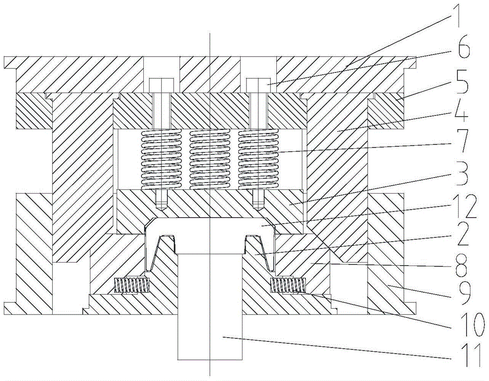
[0028] A lateral shaping process of hybrid excitation claw poles is to fix claw pole forgings on a mold, and then apply pressure to claw teeth and wings of claw poles along the radial direction of the claw poles for shaping.
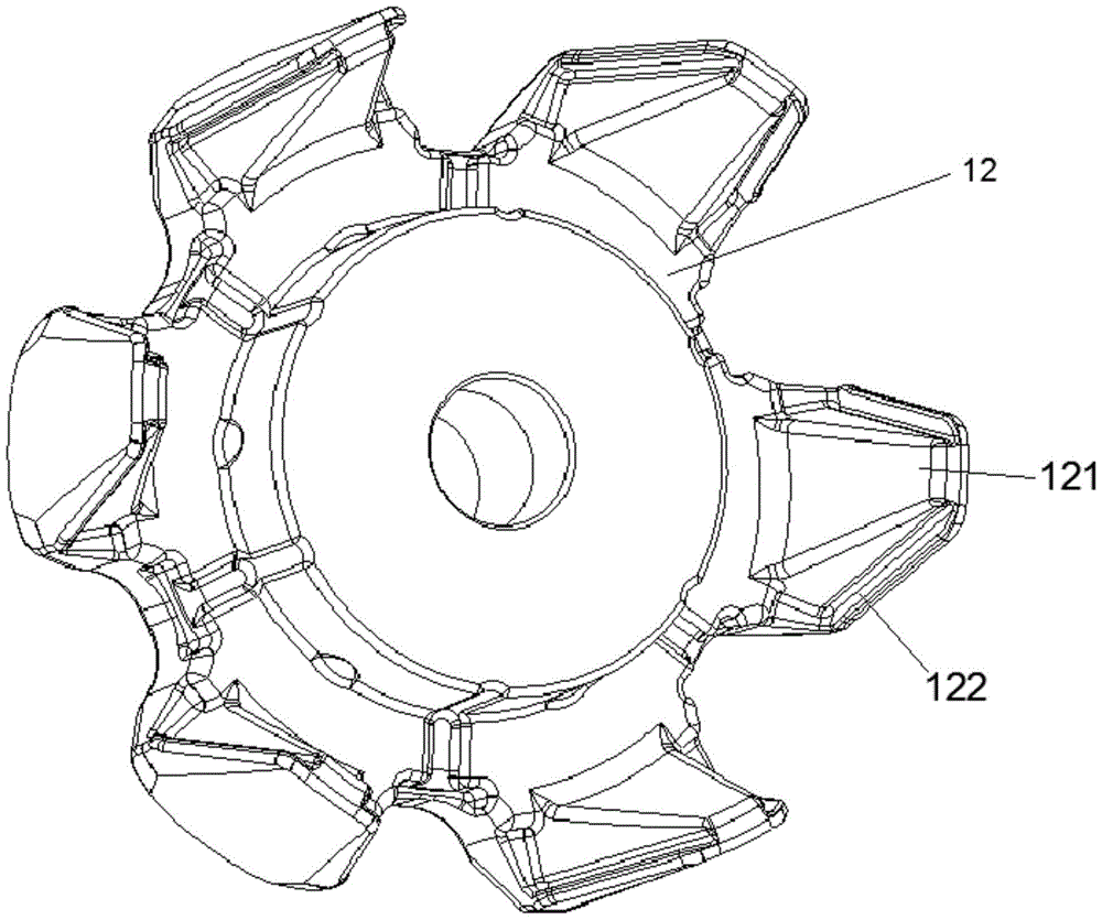
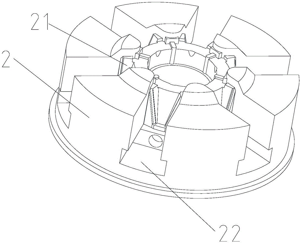
[0029] Such as figure 2 As shown, the mold for laterally shaping the hybrid excitation claw pole 12 using the above-mentioned process includes an upper mold base 1 and a lower mold base 2; an upper binder plate 3 and several wedges 4 are arranged below the upper mold base 1; The lower surface of the upper binder plate 3 is provided with an upper die, the upper die matches the shape of the upper surface of the claw pole 12, and the plurality of inclined wedges 4 are distributed on the outer side of the upper binder plate 3. The inclined wedges 4 The number is equal to the number of claw teeth 121 and wings 122 of the claw pole 12;
[0030] Such as figure 2 As shown, specifically, in order to facilitate the installation of the upper binder plate 3 and ...
PUM
 Abstract
Description
Claims
Application Information