Forging device and forging method for multi-directional die forging of large complex forgings

A complex forging, multi-directional die forging technology, applied in forging/pressing/hammer devices, manufacturing tools, forging/pressing/hammering machinery, etc. High efficiency, good quality and the effect of simplifying the forging process

Active Publication Date: 2020-06-02
TSINGHUA UNIV
View PDF7 Cites 0 Cited by
  • Summary
  • Abstract
  • Description
  • Claims
  • Application Information

AI Technical Summary

Problems solved by technology

[0007] The purpose of the present invention is to provide a forging device and forging method for multi-directional die forging for large and complex forgings, so as to solve the problem of complex forging process and small application range of forgings with boss structures in the prior art The problem

Method used


Image

  • Forging device and forging method for multi-directional die forging of large complex forgings
  • Forging device and forging method for multi-directional die forging of large complex forgings
  • Forging device and forging method for multi-directional die forging of large complex forgings

Examples


Embodiment 1

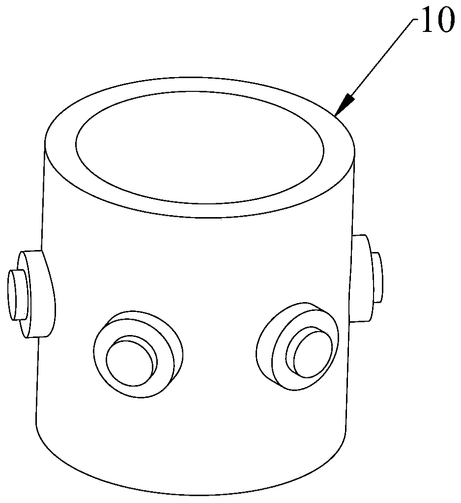
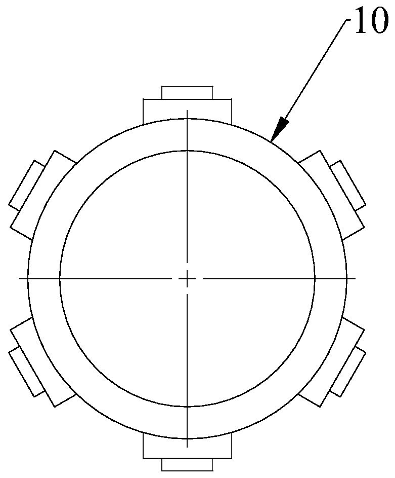
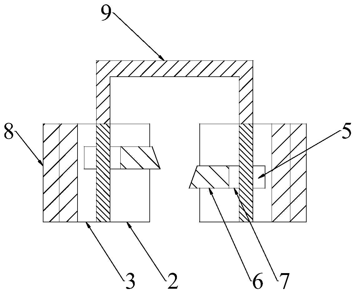
[0034] see in conjunction Figure 3 to Figure 8 , the present invention provides a multi-directional die forging forging device for large complex forgings, including a first upper die 9, a second upper die 1, a first lower die 2 and a second lower die 3; the first lower die 2 A through hole 4 is opened on the side wall of the through hole 4, and a molding pin is arranged in the through hole 4; the second lower mold 3 is detachably sleeved on the outer periphery of the first lower mold 2, and the inner surface of the second lower mold 3 is provided with a through hole 4. The die chamber 5 corresponding to the hole 4; the first upper mold 9 squeezes the blank into between the first lower mold 2 and the second lower mold 3 for arranging the blank, and the second upper mold 1 cooperates with the forming pin to push the blank A boss structure is formed in the die cavity 5 .

[0035] The forging device used for multi-directional die forging of large and complex forgings provided by...

Embodiment 2

[0052] According to another aspect of the present invention, an embodiment of the present invention also provides a forging method based on the forging device for multi-directional die forging of large complex forgings in Embodiment 1, including:

[0053] S1. Upsetting and punching the blank to form a preform;

[0054] In this step, materials such as steel ingots can be selected as the blank, and the steel ingot is upset and punched first, so as to obtain the cylinder blank;

[0055] S2. Squeeze the preform into between the first lower mold 2 and the second lower mold 3 through the first upper mold 9, so that the blank fills the gap between the first lower mold 2 and the second lower mold 3;

[0056] In this step, the preform formed in step S1 is squeezed between the first lower die 2 and the second lower die 3 through the extrusion of the first upper die 9, that is, the first upper die 9 The blank is pre-forged so that the blank fills the gap between the first lower die 2 an...


PUM


Abstract

The invention discloses a forging device and a forging method for multidirectional die forging for a large complex forged piece. The forging device comprises a first upper die, a second upper die, a first lower die and a second lower die, wherein a through hole is formed in the sidewall of the first lower die, and a forming pin is arranged in the through hole; the second lower die detachably sleeves the periphery of the first lower die, and an impression corresponding to the through hole is formed in the inner side surface of the second lower die; and the first upper die extrudes a blank intothe space between the first lower die and the second lower die, the second upper die is matched with the forming pin, and horizontal die forging is carried out on the blank to jack the blank into theimpression to form a boss structure. According to the forging device and the forging method for multidirectional die forging for the large complex forged piece, by forming the through hole in the first lower die and arranging the forming pin in the through hole, after the blank is placed, the boss structure can be formed at a position corresponding to the through hole, on the blank through the matching of the first upper die, the second upper die and the forming pin, so that the die forging for the blank in the vertical direction and the horizontal direction is realized, and a forging processfor the forged piece with the boss structure is simplified.

Description

technical field [0001] The invention relates to the technical field of mechanical processing, in particular to a forging device and a forging method for multi-directional die forging of large complex forgings. Background technique [0002] Take the complex large-scale forgings in nuclear power as an example. With the continuous improvement of nuclear reactor equipment safety and operating efficiency requirements, many nuclear power equipment parts need to be large-scaled and integrated. As the most complex and important part of the main equipment of the nuclear island One of the forgings. At present, the connecting section is often obtained by welding the nozzle and the cylinder together. Due to the large number of welds, the safety performance of the forging is greatly reduced and requires a longer inspection time, thereby reducing the cost of nuclear power equipment. operating efficiency. [0003] In a certain existing technology, the blank is processed into a cylinder wi...

Claims


Application Information

Patent Timeline
Patent Type & Authority Patents(China)
IPC IPC(8): B21J13/02B21J5/12
CPCB21J5/12B21J13/02
Inventor 吴任东袁朝龙沈泽南焦玮陈福强魏玮李滔
Owner TSINGHUA UNIV
Why Eureka
Try Eureka