An adjustable punching mechanism

An adjustable and hole-end technology, applied in the field of adjustable punching mechanism, can solve the problems of low punching efficiency and achieve the effects of easy popularization and use, low production and maintenance costs, and flexible actions

Active Publication Date: 2017-06-16
GUANGXI UNIV
View PDF4 Cites 0 Cited by
  • Summary
  • Abstract
  • Description
  • Claims
  • Application Information

AI Technical Summary

Problems solved by technology

[0005] The purpose of the present invention is to provide an adjustable punching mechanism, thereby overcoming the disadvantage of low punching efficiency of existing punching machines

Method used


Image

  • An adjustable punching mechanism
  • An adjustable punching mechanism
  • An adjustable punching mechanism

Examples


Embodiment Construction

[0021] The specific embodiments of the present invention will be described in detail below in conjunction with the accompanying drawings, but it should be understood that the protection scope of the present invention is not limited by the specific embodiments.

[0022] Unless expressly stated otherwise, throughout the specification and claims, the term "comprise" or variations thereof such as "includes" or "includes" and the like will be understood to include the stated elements or constituents, and not Other elements or other components are not excluded.

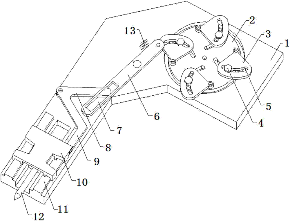
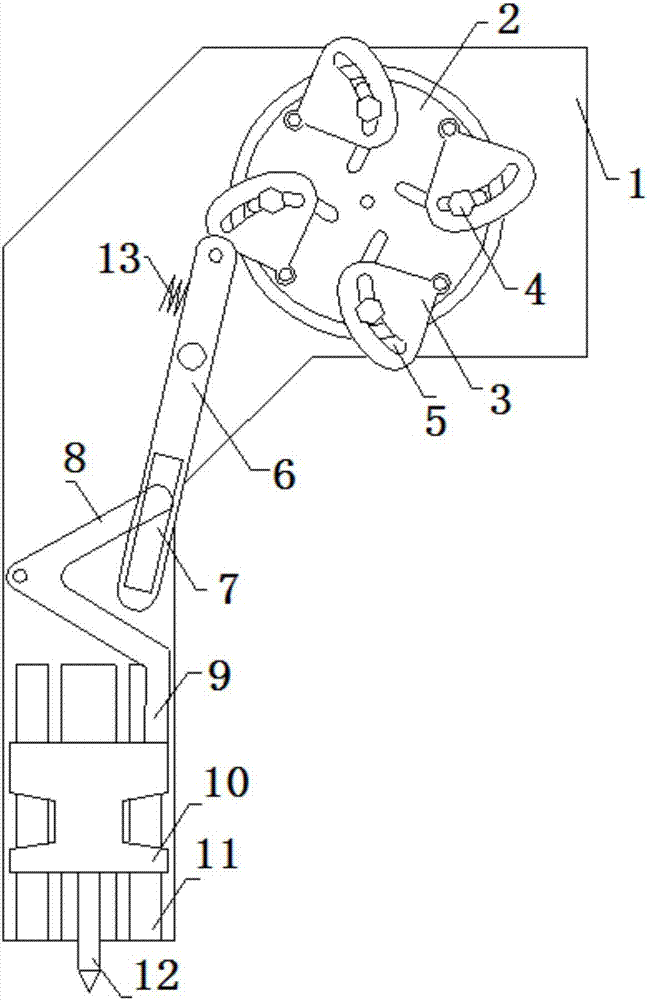
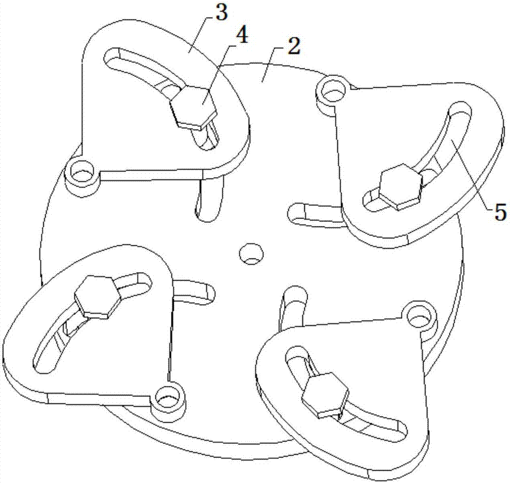
[0023] Such as Figure 1 to Figure 3 As shown, an adjustable punching mechanism according to a specific embodiment of the present invention includes: a main board 1, a punching needle 12, a runner 2, a cam 3, a cam follower 6 and a triangular rod 8; There is a driving end and a punching end; the punching needle 12 is arranged on the punching end in a manner that can slide up and down by the slide block 10, as a slide rail ...


PUM


Abstract

The invention discloses an adjustable punching mechanism, which comprises: a main board, on which a driving end and a punching end are arranged; a punching needle, which is arranged on the punching end in a manner capable of sliding up and down through a slider; A wheel, which is rotatably mounted on the driving end, is provided with a plurality of position-adjustable cams on the wheel, wherein the flanges of the cams can be adjusted in the direction extending out of the periphery of the wheel, and can be adjusted by the fixing assembly. The cam is fixed; the cam follower is hinged on the main board, and one end of the cam follower is limited by an elastic device to a position that can be engaged with the flange of the cam, and the other end is provided with a chute; and a triangular rod, whose Hinged on the main board, one end of the triangular rod is slidably set in the chute, and the other end is movably connected with the slider through a push rod; this mechanism can carry out circular drilling, and does not limit the size of the material to be punched. The material can be punched continuously, so that the punching efficiency is higher.

Description

technical field [0001] The invention relates to the field of punching, in particular to an adjustable punching mechanism. Background technique [0002] The punching machine is used for processing the holes of specific materials. It usually includes an upright fuselage and a horizontally extending head arranged on the top of the fuselage. The side of the punching machine corresponding to the outer end of the head is the punching end. The automatic punching machine is a kind of existing punching machine, which can be used for automatic punching of sheet materials. However, the traditional setting of isolated punching machines, on the one hand, a single punching machine completes the punching of the entire piece of material before proceeding to the next material, and the material is manually transferred between the punching machines, which results in low work efficiency and high labor costs; on the other hand On the one hand, for materials whose width exceeds the length of the...

Claims


Application Information

Patent Timeline
Patent Type & Authority Patents(China)
IPC IPC(8): B26F1/24B26D7/26
Inventor 李海波耿葵花王潇马小波
Owner GUANGXI UNIV
Why Eureka
Try Eureka