Ultra-short wave radio terminal testing device

A technology for ultra-short wave radio station and terminal testing, which is applied in the field of measurement, and can solve problems such as inaccurate measurement results, inability to meet high-demand fields, and difficult operation and control, and achieve superior performance, automatic calibration testing, and easy control of the measurement process.

Inactive Publication Date: 2015-12-02
成都思邦力克科技有限公司
View PDF5 Cites 10 Cited by
  • Summary
  • Abstract
  • Description
  • Claims
  • Application Information

AI Technical Summary

Problems solved by technology

However, the ultrashort wave radio station needs to be measured before it is put into use to ensure that its performance indicators meet the requirements, but now it is mainly measured during actual use. This measurement method is not easy to operate and control, and the measurement results are not accurate, so it cannot meet some high-demand fields. needs

Method used


Image

  • Ultra-short wave radio terminal testing device

Examples


Embodiment 1

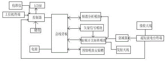
[0015] like figure 1 As shown, the present invention includes a controller, a bus backplane, a calibrator and an ultrashort wave radio station terminal, the bus backplane is connected to the controller, and a spectrum analysis module, a vector signal module and a radio frequency switch matrix are also connected on the bus backplane module, wherein the radio frequency switch matrix module is also connected to the spectrum analysis module and the vector signal module at the same time, the ultrashort wave radio terminal and the radio frequency switch matrix module are connected through an attenuator, and the radio frequency switch matrix module is also connected to the transmitting antenna; the ultrashort wave radio terminal At the same time, the controller is connected, and the ultrashort wave radio terminal is also connected to the receiving antenna; the controller is also connected with an LCD screen, a calibrator and an ultrashort wave radio terminal.

[0016] This tester is ...

Embodiment 2

[0018] This embodiment is preferably as follows on the basis of the above embodiments: In order to facilitate the observation of the measurement results and realize the test with the external network, the controller is connected to the host computer terminal through the 100M network port, and a keyboard is also connected to the controller.

[0019] The bus backplane is also connected with a reserved module installation slot and a 220V power supply.

[0020] The attenuator is a 50W attenuator. In order to meet the level requirements of the port and avoid damage to the RF switch matrix module due to excessive levels.

[0021] An RS232 interface is also provided on the controller. The ultrashort wave radio terminal is also connected to the controller through the RS232 interface to realize the control of the ultrashort wave radio by the controller, thereby realizing closed-loop measurement, avoiding external signal interference, and more accurate measurement results.


PUM


Abstract

The present invention discloses an ultra-short wave radio terminal testing device which comprises a controller, a bus backplane, a calibrator and an ultra-short wave radio terminal. The bus backplane is connected to the controller and is also connected to a spectrum analysis module, a vector signal module and an RF switch matrix module at the same time. The RF switch matrix module is also connected to the spectrum analysis module and the vector signal module at the same time. The ultra-short wave radio terminal and the RF switch matrix module are connected through an attenuator. The RF switch matrix module is also connected to a transmitting antenna. The ultra-short wave radio terminal is connected to the controller and a receiving antenna at the same time. The controller is connected to an LCD screen, the calibrator and the ultra-short wave radio terminal. According to the ultra-short wave radio terminal testing device, through the above principle, the closed-loop measurement is used, the measurement process is easy to control, an automatic calibration test can be achieved, test result information is more stable and reliable, and the performance of a produced ultra-short wave radio terminal is more superior.

Description

technical field [0001] The invention relates to the field of measurement, in particular to an ultrashort wave radio terminal testing device. Background technique [0002] Ultrashort wave radio communication equipment with a working wavelength of 10 to 1 meter (frequency of 30 to 300 MHz). Strictly speaking, all relays, scattering machines, and meteor trail communication equipment that work in this band belong to ultrashort wave radio stations. But it usually refers to walkie-talkies, portable, vehicle-mounted (or airborne, ship-borne) radios that are transmitted by ground wave or space wave line-of-sight. It is mainly composed of transceivers, antennas and power supplies. Ultra-short wave radio stations can use AM, FM, SSB and other modulation systems, usually FM-based, and its anti-interference performance is better than AM and SSB. Compared with short-wave radio, ultra-short-wave radio has the advantages of communication frequency bandwidth, large capacity, and stable si...

Claims


Application Information

Patent Timeline
Patent Type & Authority Applications(China)
IPC IPC(8): H04B17/29H04B17/15
Inventor 罗庆罗世培聂龙华沈军叶富强刘刚庞平
Owner 成都思邦力克科技有限公司
Why Eureka
Try Eureka