A design method of armored mud discharge pipe and its mud discharge pipe

A design method and technology of sludge discharge pipe, applied in the direction of pipes/pipe joints/pipes, hoses, pipes, etc., can solve the problem that the conveying resistance affects the conveying speed, the wear resistance of the inner pipe wall is different, and the bending degree cannot be guaranteed. and other problems, to achieve the effect of ensuring wear resistance, novel design concept, and meeting bending requirements

Active Publication Date: 2017-04-05
姜考成
View PDF2 Cites 0 Cited by
  • Summary
  • Abstract
  • Description
  • Claims
  • Application Information

AI Technical Summary

Problems solved by technology

However, due to the product defects of the self-floating mud discharge rubber pipe itself, there are the following deficiencies: First, although the self-floating mud discharge rubber pipe has a certain bending performance, due to the adjustment of the curvature of the mud discharge pipeline direction It is realized by the overall deformation scheme from the inside to the outside. For the self-floating mud discharge rubber pipe, this deformation is completed by the elastic deformation of each part of the pipe body, and the elastic deformation of each part is for the pipe body. For the same circular section, there are double stresses of tension and compression, so this technical solution itself exists in the absence of bending external force, the self-floating mud discharge rubber pipe depends on the elastic deformation of its own rubber products It is the defect that it cannot guarantee to meet the requirements of the bending degree, especially when it is used in conjunction with the bundled floating metal mud discharge pipe, the non-matching defect is more prominent; the second is that the self-floating mud discharge rubber pipe passes through The technical solution of adding organic adhesive and wear-resistant steel ring to the innermost layer of the rubber hose can improve the wear resistance of the rubber hose. When the self-floating mud discharge rubber hose is in use, the solid material to be transported is in an organic adhesive. The pipeline composed of wear-resistant steel rings runs repeatedly. Since the inner wall made of organic adhesives and wear-resistant steel rings will be repeatedly collided by solid materials, the degree of wear of organic adhesives and wear-resistant steel rings is different. This will not only affect the conveying speed due to conveying resistance, but also directly affect the service life. Due to the inconsistent wear resistance of the inner pipe wall, it is difficult to use it with a better metal composite mud discharge pipe, especially in the harsher working environment. This unmatched phenomenon is more prominent when transporting ore ore or coral reefs in the South China Sea; therefore, how to provide a new design method based on the existing technology to design and manufacture a new mud discharge pipeline An armored mud discharge pipe not only satisfies the purpose of adjusting the direction of the mud discharge pipeline, but also achieves the wear resistance similar to that of the metal composite mud discharge pipe, comprehensively improves the service life of the metal mud discharge pipe, and reduces the cost of dredging projects. production cost, improve the economic benefit of the enterprise, this is indeed a technical problem to be solved urgently for those skilled in the art

Method used


Image

  • A design method of armored mud discharge pipe and its mud discharge pipe
  • A design method of armored mud discharge pipe and its mud discharge pipe
  • A design method of armored mud discharge pipe and its mud discharge pipe

Examples


Embodiment 1

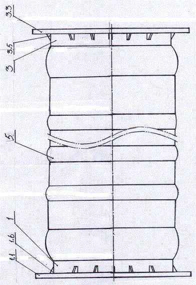
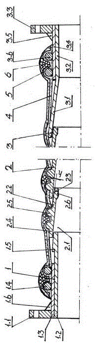
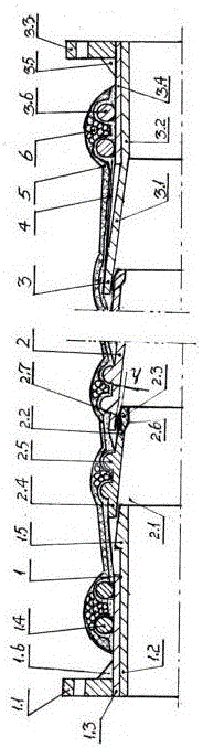
[0030] The design method of a kind of armored mud discharge pipe of embodiment 1 of the present invention, comprises the overall design of inlet end pipe, armored pipe body and outlet end connection pipe and the specific design of each component, the armored mud discharge pipe of described The design method is based on the premise of meeting the technical requirements of the bending degree ≥ 35°, and adopts an overall design scheme of front and rear armored sleeves for the inlet end pipe, armored pipe body and outlet end pipe. The details include: the inlet end pipe It is a casing that combines the inner and outer tubes and has a flange at the inlet end, two ring-shaped positioning fastening rings on the outside, and a tapered boss on the outside of the outlet end and is inserted into the armored tube body. The inner cavity of the inlet end; the armored pipe body is connected by a plurality of conical pipes. The diameter of the cavity is the outlet end, and the outlet end of t...

Embodiment 2

[0045] The design method of a kind of armored mud discharge pipe of the embodiment 2 of the present invention, comprises the overall design and the specific design of each parts of the inlet end pipe, the armored pipe body and the outlet end pipe, the armored pipe described in the embodiment 2 of the present invention The design method of the mud discharge pipe is based on the premise of meeting the technical requirements of the bending degree ≥ 35°. The overall design scheme of the front and rear armored sleeves is adopted for the inlet end pipe, armored pipe body and outlet end pipe. The details are as follows: The inlet-end connection pipe described above is a casing that combines inner and outer pipes, and a flange is provided at the inlet end, and two ring-shaped positioning fastening rings are arranged on the outer side, and a tapered boss is arranged on the outer side of the outlet end for insertion. In the inner cavity of the entrance end of the armored pipe body; the a...

Embodiment 3

[0061] A design method of an armored mud discharge pipe according to Embodiment 3 of the present invention, including the overall design of the inlet end pipe, the armored pipe body and the outlet end pipe, and the specific design of each part. The armored pipe described in Embodiment 3 of the present invention The design method of the mud discharge pipe is based on the premise of meeting the technical requirements of the bending degree ≥ 35°. The overall design scheme of the front and rear armored sleeves is adopted for the inlet end pipe, armored pipe body and outlet end pipe. The details are as follows: The inlet-end connection pipe described above is a casing that combines inner and outer pipes, and a flange is provided at the inlet end, and two ring-shaped positioning fastening rings are arranged on the outer side, and a tapered boss is arranged on the outer side of the outlet end for insertion. In the inner cavity of the entrance end of the armored pipe body; the armored ...


PUM


Abstract

The invention discloses a method of designing a cladded mud dredging pipe and mud a dredging pipe utilizing the same and employed in a dredging process. The method is adopted, with meeting a technical requirement of providing a curvature exceeding or equal to 35° in mind, to design an inlet connection pipe, a cladded main pipe, and an outlet connection pipe of the cladded mud dredging pipe, wherein each component is cladded and fit to each other. The inlet connection pipe (1) of the mud dredging pipe is a pipe set including an inner pipe and an outer pipe integrated to each other, and comprises an output outer side inserted in an input inner cavity (2.1) of the cladded main pipe (2). The cladded main pipe (2) comprises a plurality of conical pipes (2.2) inserted into and connected to one another. The outlet connection pipe (3) comprises an inner pipe, wherein an inverted conical pipe (3.1) of the inner pipe is fit to an output outer side of the cladded main pipe (2), and an outer side of the inner pipe is integrated with an outer pipe (3.4). In comparison to prior art, the mud dredging pipe can meet a curvature requirement necessary for adjusting a pipeline direction of the mud dredging pipes, and has wear resistance close to that of a metal composite mud dredging pipe, enhancing overall application performance of a metal mud dredging pipe.

Description

technical field [0001] The invention relates to the technical field of related equipment used in dredging engineering, in particular to a design method of an armored mud discharge pipe used in dredging engineering and the technical field of the mud discharge pipe. Background technique [0002] Mechanical dredging projects such as river courses, waterways, harbor basin dredging, harbor shoals, and wharf foundation trenches all require a large number of mud discharge pipelines connected by mud discharge pipes to achieve transportation, and the indispensable part of the entire mud discharge pipeline is used to adjust The mud discharge elbow in the direction of the mud discharge pipeline, most of the self-floating mud discharge rubber pipes that have been used so far, because the self-floating mud discharge rubber pipe is very fast when transporting solid materials with sharp edges such as rocks, coral reefs, ores, etc. It will be worn out and lose its use value, which will lead...

Claims


Application Information

Patent Timeline
Patent Type & Authority Patents(China)
IPC IPC(8): F16L11/08F16L11/133E02F7/10
CPCF16L11/08
Inventor 姜考成唐永胜陈宏礼姜作亮
Owner 姜考成
Why Eureka
Try Eureka