Discharging device and discharging method of suspended centrifugal casting machine

A centrifugal pouring and unloading device technology, which is applied in the unloading device and unloading field, can solve the problems of high physical endurance requirements for staff, reduce equipment processing efficiency, and increase production costs of enterprises, so as to avoid human eye injuries, Reduce the frequency of replacement and achieve the effect of safe production

Active Publication Date: 2016-01-13
CRRC QISHUYAN INSTITUTE CO LTD +1
View PDF4 Cites 2 Cited by
  • Summary
  • Abstract
  • Description
  • Claims
  • Application Information

AI Technical Summary

Problems solved by technology

[0003] In order to produce large-diameter cylinder rings, hydraulic cylinders are used as power for the ejection of the unloading parts, and the jacking force is large. The rated ejection force of the machine is 40000N. The force is so strong that the operator has no time to clamp the cylinder ring with a special clamp and drag it out slowly. Therefore, the cylinder ring is easy to pop out of the centrifugal casting machine and burn the operator. There are many potential safety hazards and the degree of automation is low.
[0004] And because the thrust of the push rod is relatively large, when the cylinder ring encounters the resistance of the baffle during the pushing out process of the cylinder ring, it is very easy to bend the transmission shaft. At this time, the shaft needs to be replaced again, which not only causes economic losses, but also increases The production cost of the enterprise, frequent shaft replacement will also reduce the processing efficiency of the entire equipment
[0005] Furthermore, since the quality of castings is generally between 20 kg and 150 kg, and the weight is large, manual clamping with special fixtures is labor-intensive, low-efficiency, and requires high physical endurance of the staff, which is difficult for ordinary workers to perform.

Method used


Image

  • Discharging device and discharging method of suspended centrifugal casting machine
  • Discharging device and discharging method of suspended centrifugal casting machine
  • Discharging device and discharging method of suspended centrifugal casting machine

Examples


Embodiment 1

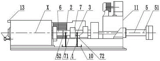
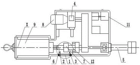
[0033] A hanging type centrifugal pouring machine unloading device disclosed in this embodiment, as attached figure 2 As shown, it includes a suspended centrifugal pouring machine 11, and the suspended centrifugal pouring machine 11 includes a discharge port, a push rod 5, a hydraulic cylinder 8 that drives the push rod 5 to reciprocate, and a control that controls the operation of the hydraulic cylinder 8. device 4.

[0034] The discharge port is located at one end of the suspended centrifugal casting machine 11 in the X-axis direction, the processed cylinder ring casting 9 is located in the discharge port, and a baffle is also arranged at the exit of the discharge port; The initial end 51 of the push rod 5 is located outside the other end of the suspended centrifugal pouring machine 11 in the X-axis direction, and the extension end 52 of the push rod 5 is connected to the transmission shaft 6 through a quick-change joint. The push rod 5 enters or exits the discharge port d...

Embodiment 2

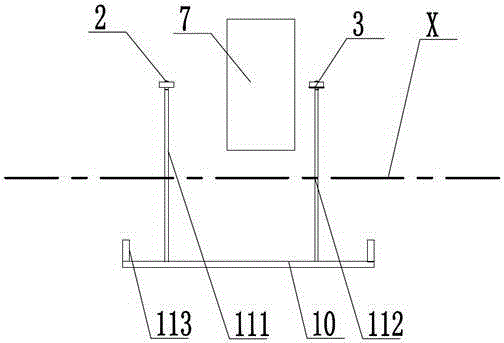
[0055] The overall structure of this embodiment is similar to that of Embodiment 1, the difference is that: Figure 5 As shown, the stroke adjustment bracket 1 includes a flat plate 15, the flat plate 15 is set on the suspended centrifugal pouring machine 11 through at least one support frame, and the flat plate 15 is provided with a chute 16 of a specified length in the X-axis direction , the length of the chute 16 is consistent with the length of the chute on the bottom plate 10 in Embodiment 1, the feed termination contact 2 and the withdrawal termination contact 3 can be slidably arranged on the chute, the The flat plate 15 is provided with a scale line 17, according to the scale line 17, by manually sliding the feed stop contact 2 and the retreat stop contact 3, the precise adjustment of the distance between them can be realized.

[0056] The working process of this implementation is similar to the process of embodiment 1, the difference is that: the adjustment process of...


PUM


Abstract

The invention discloses a discharging device and discharging method of a suspended centrifugal casting machine. The suspended centrifugal casting machine is involved, and comprises a push rod, a hydraulic oil cylinder for driving the push rod to reciprocate and a control device for controlling the working of the hydraulic oil cylinder; a limiting mechanism for controlling advancing and retreating travels of the push rod and a workpiece sensing device are further arranged on the suspended centrifugal casting machine; the limiting mechanism and the workpiece sensing device are electrically connected with the control device, respectively, and transmit working signals for starting and stopping the hydraulic oil cylinder to the control device. The suspended centrifugal casting machine is reasonable in design, exquisite in structure, safe and reliable and convenient to operate; the hydraulic oil cylinder is controlled through a stopping signal so that a pushing distance of the push rod is controlled; the problem that a small-diameter barrel ring is ejected to burn the working personnel under a great ejection force is avoided, and the service life of a shaft can be greatly prolonged through travel control and the replacement frequency of the shaft is reduced; as a result, the double effects of safe production and economic benefit increase are achieved.

Description

technical field [0001] The invention relates to a discharge device and a discharge method, in particular to a discharge device and a discharge method of a suspended centrifugal glue injection machine. Background technique [0002] At present, the centrifugal casting machine is mainly used to produce cylindrical piston rings of various diameters, the diameter size is from 200mm-900mm, the height is 200mm-500mm, and the casting quality is from 20kg-150kg. [0003] In order to produce large-diameter cylinder rings, hydraulic cylinders are used as power for the ejection of the unloading parts, and the jacking force is large. The rated ejection force of the machine is 40000N. The force is so strong that the operator has no time to clamp the cylinder ring with a special clamp and drag it out slowly. Therefore, the cylinder ring is easy to pop out of the centrifugal casting machine and burn the operator. There are many potential safety hazards and the degree of automation is low. ...

Claims


Application Information

Patent Timeline
Patent Type & Authority Applications(China)
IPC IPC(8): B22D13/10
Inventor 刘宇谢明义付玉龙
Owner CRRC QISHUYAN INSTITUTE CO LTD
Why Eureka
Try Eureka