Welding equipment structure

A technology of welding equipment and welding torch, which is applied in the field of welding equipment structure, and can solve problems such as large volume and weight, high load duration, and difficulty in moving

Active Publication Date: 2016-03-23
SHANGHAI HUGONG ELECTRIC WELDING MACHINE MFG
View PDF6 Cites 2 Cited by
  • Summary
  • Abstract
  • Description
  • Claims
  • Application Information

AI Technical Summary

Problems solved by technology

[0002] Among the existing products, MIG / MAG welding equipment is powered by a three-phase power supply, with high load duration, complex product processing technology and structure, relatively large volume and weight, difficult to move, and high cost, which is not suitable for mass production and Single-phase power supply for household maintenance and overseas markets

Method used


Image

  • Welding equipment structure
  • Welding equipment structure
  • Welding equipment structure

Examples


Embodiment Construction

[0046] The advantages of the present invention will be further elaborated below in conjunction with the accompanying drawings and specific embodiments.

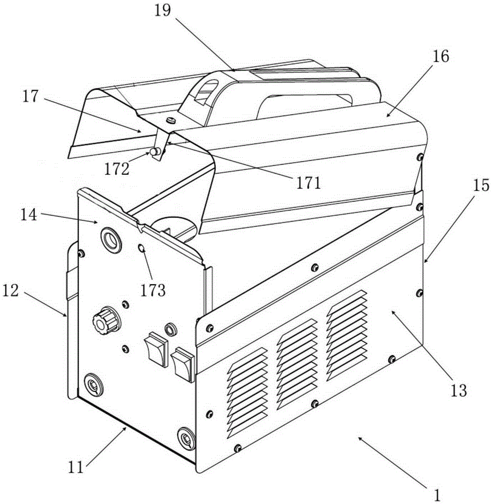
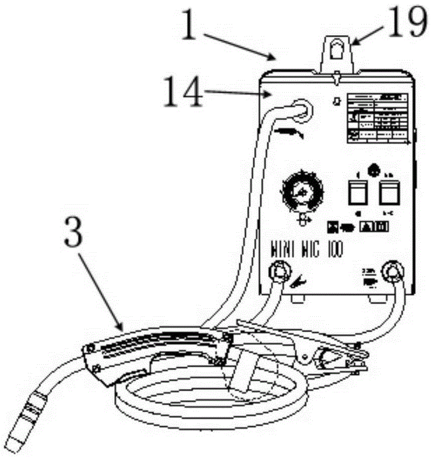
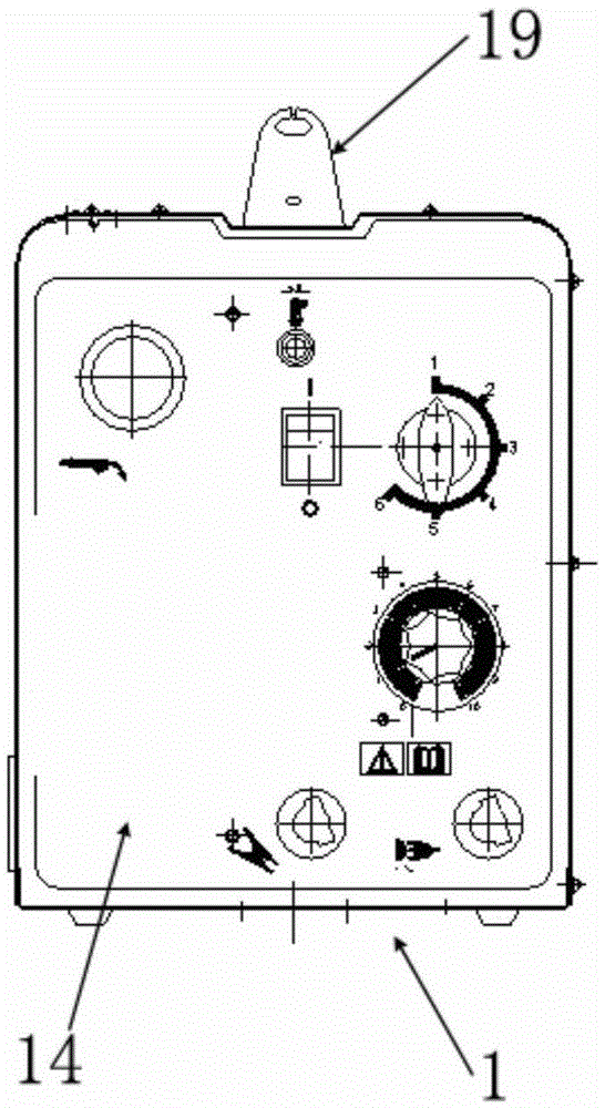
[0047] The invention discloses a welding equipment structure, including a wire feeding device 2, a welding torch 3 and a housing 1, wherein, such as figure 1 As shown, the housing 1 is a cube, including an accommodating portion composed of a bottom plate 11, a left side plate 12, a right side plate 13, a front plate 14, and a rear plate 15, and a flap plate that can be opened and closed relative to the accommodating portion. 16.

[0048] A fastening connection device 17 is disposed on the flip panel 16 adjacent to the front panel 14 . Wherein, the fastening connection device 17 includes an elastic element 171 fixed on the flip panel 16, a protruding part 172 fixed on the elastic element 171 close to the free end of the elastic element 171 and protruding outward, and a protruding part 172 arranged on the front plate 14 and pr...


PUM


Abstract

The invention provides a welding equipment structure which comprises a wire feeding device, a welding gun and a shell. The welding equipment structure is characterized in that the shell is a cuboid and comprises a containing part and a turning cover board, wherein the containing part is composed of a bottom board, a left side board, a right side board, a front board and a rear board, and the turning cover board can be opened and closed relative to the containing part. A buckling connecting device is arranged at the end, close to the front board, of the turning cover board and comprises an elastic element fixed to the turning cover board, a protruding part fixed to the portion close to the free end of the elastic element and protruding outwards and a kidney-shaped hole formed in the front board and corresponding to the protruding part.

Description

technical field [0001] The invention relates to a welding equipment structure. Background technique [0002] Among the existing products, MIG / MAG welding equipment is powered by a three-phase power supply, with high load duration, complex product processing technology and structure, relatively large volume and weight, difficult to move, and high cost, which is not suitable for mass production and Home maintenance on single-phase power supply as well as overseas markets. Contents of the invention [0003] In order to overcome the above-mentioned technical defects, the object of the present invention is to provide an energy-saving, material-saving, advanced structure, low cost, light weight, convenient movement, convenient and practical control, stable welding performance, suitable for mass production, reliable and practical single-phase power supply welding equipment structure. [0004] The invention discloses a structure of welding equipment, which includes a wire feedin...

Claims


Application Information

Patent Timeline
IPC IPC(8): B23K9/00B23K9/32B23K9/133B23K9/28
CPCB23K9/00B23K9/1336B23K9/28B23K9/32
Inventor 不公告发明人
Owner SHANGHAI HUGONG ELECTRIC WELDING MACHINE MFG
Why Eureka
Try Eureka