Valve arrangement

A technology of valve device and driving device, which is applied in the direction of valve device, valve operation/release device, valve details, etc., and can solve problems such as damage to operating performance and large dead point volume

Inactive Publication Date: 2016-04-06
FESTO AG & CO KG
View PDF4 Cites 6 Cited by
  • Summary
  • Abstract
  • Description
  • Claims
  • Application Information

AI Technical Summary

Problems solved by technology

Although the known valve device has the advantage that the movable coil unit can have a small movement scale, which contributes to the response performance, it is limited by the relatively complex mechanical structure of the moving assembly, and the valve device has Relatively large dimensions and the need for a large-volume receiving cavity for housing the moving components, thus resulting in a large dead volume, which impairs the dynamics of the running performance (Dynamik)

Method used


Image

  • Valve arrangement
  • Valve arrangement
  • Valve arrangement

Examples


Embodiment Construction

[0037] The valve device, which is identified in its general aspect with the reference number 1 , serves to control the flow of a fluid, in particular a gaseous fluid, and here preferably compressed air. However, the valve arrangement can also be used to control liquid media.

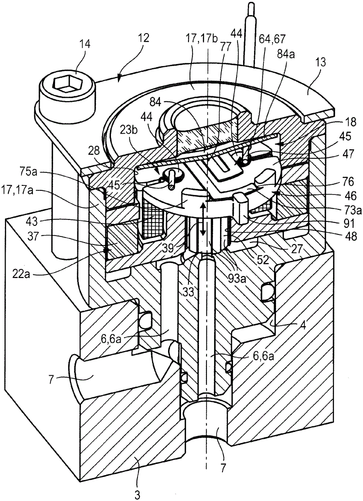
[0038] The valve device 1 has a valve unit 2 which can be used alone or preferably in combination with a connecting body 3 with which it can form a subassembly. The connecting body 3 has a blind hole-shaped receptacle 4 , into which the valve unit 2 can be inserted in a sealed manner in the manner of a bullet casing with a seat section 5 . figure 1 and figure 2 The valve device 1 is shown in the joined state of the subassembly consisting of the valve unit 2 and the connecting body 3 .

[0039] A plurality of valve channels 6 extend in the valve unit 2 . The valve channels 6 respectively communicate with one of a plurality of connecting channels 7 , which pass through the connecting body 3 . Each con...


PUM


Abstract

The invention relates to a valve arrangement (1) which has a valve unit (2) with an electrodynamic drive device (22). The latter contains an annular permanent magnet unit (22a) and a coil unit (23b) which can be moved in a linear manner relative to the permanent magnet unit, thereby carrying out a drive movement (39), and which has a coil (43) that interacts with the permanent magnet unit (22a). The coil (43) is arranged on a coil support (46) of the drive unit (23b), a column-shaped guide portion (52) of said coil support being immersed into a central guide through-opening (48) of the permanent magnet unit (22a) and said coil support being paired with a closure means (34) which cooperates with a valve seat (33). As a result of the interaction between the guide portion (52) and the permanent magnet unit (22a) in the region of the guide through-opening (48), a linear guide is provided for the coil unit (23b) such that a precise valve function can be ensured with compact dimensions.

Description

technical field [0001] The invention relates to a valve device having at least one electrically actuatable valve unit with an electric drive arranged in a valve housing, the drive having a fixed position with respect to the valve housing and a ring-shaped permanent magnet unit containing at least one permanent magnet; and a coil unit having a coil that is also ring-shaped and coaxially inserted into the ring-shaped permanent magnet unit, wherein the coil can be energized so that The coil unit is driven in a drive movement relative to the permanent magnet unit, wherein the valve unit also has a closing element, which is opposite a valve seat assigned to the valve channel, and which closes by means of Kinematically coupled to a coil carrier of the coil unit carrying the coil: the closing element can be positioned relative to the valve seat by a drive movement of the coil unit in order to selectively close or open the associated valve channel. Background technique [0002] A v...

Claims


Application Information

Patent Timeline
Patent Type & Authority Applications(China)
IPC IPC(8): F16K31/06
CPCF16K31/082F16K31/0655
Inventor G.门兹M.伦兹J.沙伊佩勒
Owner FESTO AG & CO KG
Why Eureka
Try Eureka