Butterfly valve for water storage tank

A water storage tank and butterfly valve technology, applied in the direction of lift valve, valve details, valve device, etc., can solve the problems of reducing the service life of the butterfly valve, easy to damage the valve core, easy to cause cavitation, etc., to stabilize the water flow in the pipe and improve the filtration efficiency. , the effect of reducing cavitation

Inactive Publication Date: 2016-06-29
陈杰
View PDF8 Cites 7 Cited by
  • Summary
  • Abstract
  • Description
  • Claims
  • Application Information

AI Technical Summary

Problems solved by technology

[0003] Ordinary butterfly valves for water storage tanks have the following defects: 1. The valve stem passes through the butterfly plate and is connected to the valve core, which is prone to leakage between the valve stem and the packing; 2. Cavitation is prone to occur when water flows through the ordinary butterfly valve, reducing the service life; three, the inflow of water is not filtered, easy to damage the valve core

Method used


Image

  • Butterfly valve for water storage tank
  • Butterfly valve for water storage tank
  • Butterfly valve for water storage tank

Examples


Embodiment Construction

[0029] The present invention will be further described below in conjunction with drawings and embodiments.

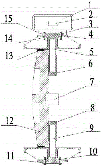
[0030] like figure 1 As shown, the present invention has a valve body 4, an electromagnetic controller 1 is installed on the valve body 4, an electromagnet 2 is built in the electromagnetic controller 1, and a butterfly plate 12 with a permanent magnet 7 is installed in the inner cavity of the valve body 4. Drive the rotation of butterfly plate 12;

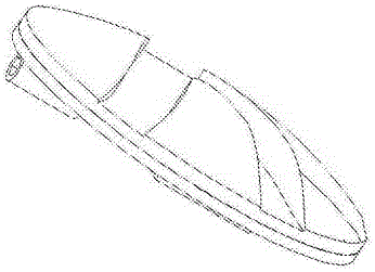
[0031] Upper bonnet 14 and lower bonnet 11 are respectively fixed on the upper and lower ends of valve body 4 by bolt 3, as Figure 5-6 As shown, the permanent magnet 7 is fixed in the middle of one end face of the butterfly plate 12, and the upper and lower parts of the end face of the butterfly plate 12 where the permanent magnet 7 is located are respectively fixed with a coaxial upper bushing 6 and a lower bushing 8, so that the butterfly plate 12 and the upper The valve stem 5 and the lower valve stem 9 are connected ...


PUM


Abstract

The invention discloses a butterfly valve of a water storage tank. An electromagnetic controller is mounted on a valve body, a butterfly plate with a permanent magnet is mounted in an inner cavity of the valve body; upper valve covers are respectively fixed to the upper end of the valve body, lower valve covers are respectively fixed to the lower end of the valve body, and the permanent magnet is fixed to the middle part of one end surface of the butterfly plate; an upper shaft sleeve and a lower shaft sleeve are coaxial, the upper shaft sleeve is fixed to the upper part of the end surface, on which the permanent magnet is positioned, of the butterfly plate, and the lower shaft sleeve is fixed to the lower part of the end surface, on which the permanent magnet is positioned, of the butterfly plate; the upper shaft sleeve is in matching connection with the upper valve covers through an upper valve rod, and the lower shaft sleeve is in matching connection with the lower valve covers through a lower valve rod; an inlet flow channel and two outlet flow channels are arranged on the other end surface of the butterfly plate; an inlet filter pipe is also connected to the inlet flow channel. According to the butterfly valve disclosed by the invention, the situation of leakage between the valve rods and fillings is avoided, besides, a gaseous cavitation preventing flow channel is processed on the surface of the butterfly plate, and one side of the butterfly plate is a spherical protrusion. The butterfly valve has the effects of shunting decompressing, reducing gaseous cavitation, preventing vibration and reducing noise, and the service life of the butterfly valve is prolonged. On the other hand, the inlet filter pipe has the effects of filtering water flows, and preventing valve cores from being destroyed.

Description

technical field [0001] The invention discloses a butterfly valve, in particular to a butterfly valve for a water storage tank. Background technique [0002] Butterfly valve, also known as flap valve, is a regulating valve with simple structure and is a common device for water storage tanks. [0003] Ordinary butterfly valves for water storage tanks have the following defects: 1. The valve stem passes through the butterfly plate and is connected to the valve core, which is prone to leakage between the valve stem and the packing; 2. Cavitation is prone to occur when water flows through the ordinary butterfly valve, reducing the Third, the inflow of water is not filtered, easy to damage the valve core. Contents of the invention [0004] The object of the present invention is to provide a butterfly valve for a water storage tank, which can reduce the leakage between the valve stem and the filler, reduce cavitation, improve the service life, and at the same time realize the fi...

Claims


Application Information

Patent Timeline
Patent Type & Authority Applications(China)
IPC IPC(8): F16K1/22F16K1/36F16K31/08F16K47/02F16K47/06B01D35/04
CPCF16K1/221B01D35/046F16K1/222F16K31/088F16K47/023F16K47/06
Inventor 陈杰
Owner 陈杰
Why Eureka
Try Eureka