Drive axle with wet brakes and sectional axle housings

A wet brake and segmented technology, which is applied in the transmission system field of transport vehicles, can solve the problems that the brakes are sticky with mud, it is difficult to remove, the brake shoe friction plate is easy to crack, and the brake stability is affected, so as to achieve low noise, Simple structure, low maintenance cost

Inactive Publication Date: 2016-07-13
ANHUI HELI CO LTD
View PDF8 Cites 1 Cited by
  • Summary
  • Abstract
  • Description
  • Claims
  • Application Information

AI Technical Summary

Problems solved by technology

[0002] At present, the commonly used drive axles generally adopt drum brakes. The drum brakes have a simple structure and low cost, but the drum brakes have the following disadvantages: 1. The brake shoe friction plate is easy to crack and ablate; 2. The brake sticks It is difficult to remove mud, water, oil, etc., which affects the stability of braking; 3. The braking area is small, resulting in unstable braking force and poor heat dissipation; 4. Most of the existing drive axles use integral cast axle housings or Welded axle housing, its casting process is not good, it is not easy to process, and it is easy to produce waste products

Method used


Image

  • Drive axle with wet brakes and sectional axle housings
  • Drive axle with wet brakes and sectional axle housings
  • Drive axle with wet brakes and sectional axle housings

Examples


Embodiment Construction

[0024] The present invention will be further described below in conjunction with accompanying drawing:

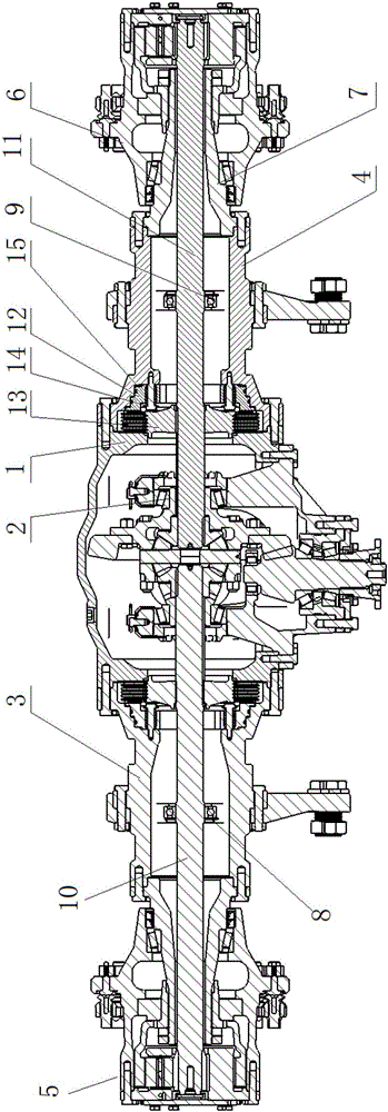
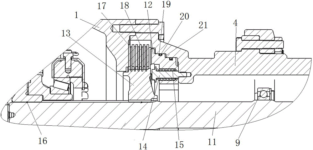
[0025] Such as Figure 1-Figure 4 The drive axle with wet brake and segmented axle housing shown includes a middle axle housing 1, a differential assembly 2 embedded in the middle axle housing 1, a symmetrically arranged left half shaft 10 and a right axle housing. The half shaft 11, the left axle housing 3 and the right axle housing 4 symmetrically arranged on the left and right sides of the middle axle housing 1 from the inside to the outside, and the left wheel side reducer assembly 5 and the right wheel side reducer assembly 6, and symmetrically arranged and The left wet brake and the right wet brake are respectively located inside the junction of the middle axle housing 1 and the left axle housing 3, and inside the junction of the middle axle housing 1 and the right axle housing 4. A shaft head 7 is respectively provided between the left axle housing 3 and the left wh...


PUM


Abstract

The invention relates to a drive axle with wet brakes and sectional axle housings. The drive axle comprises an intermediate axle housing, a differential assembly, a left semi-axle, a right semi-axle, a left axle housing, a right axle housing, a left wheel side speed reducer assembly, a right wheel side speed reducer assembly, a left wet brake and a right wet brake, wherein the differential assembly is embedded and mounted into the intermediate axle housing; the left axle housing and the right axle housing, as well as the left wheel side speed reducer assembly and the right wheel side speed reducer assembly are sequentially and symmetrically arranged on the left side and the right side of the intermediate axle housing from inside to outside; the left wet brake and the right wet brake are symmetrically arranged and respectively located on the inner side of a joint between the intermediate axle housing and the left axle housing and on the inner side of a joint between the intermediate axle housing and the right axle housing; one end of the left semi-axle is connected with the differential assembly, and the other end penetrates the left wet brake and the left axle housing sequentially, and is then connected with the left wheel side speed reducer assembly; one end of the right semi-axle is connected with the differential assembly, and the other end penetrates the right wet brake and the right axle housing sequentially, and is then connected with the right wheel side speed reducer assembly. The drive axle has the characteristics of being stable in brake performance, uniform in stress to paired friction parts, convenient to machine, low in rejection rate and the like.

Description

technical field [0001] The invention relates to the technical field of transmission systems of transport vehicles, in particular to a drive axle with wet brakes and segmented axle housings. Background technique [0002] At present, the commonly used drive axles generally adopt drum brakes. The drum brakes have a simple structure and low cost, but the drum brakes have the following disadvantages: 1. The brake shoe friction plate is easy to crack and ablate; 2. The brake sticks It is difficult to remove mud, water, oil, etc., which affects the stability of braking; 3. The braking area is small, resulting in unstable braking force and poor heat dissipation; 4. Most of the existing drive axles use integral cast axle housings or Welded axle housings have poor casting process, are not easy to process, and are prone to waste products. Contents of the invention [0003] The purpose of the present invention is to provide a drive axle with wet brake and segmented axle housing, ...

Claims


Application Information

Patent Timeline
IPC IPC(8): B60T1/06B60B35/16B60B35/14B60K17/06B60K17/16
CPCB60T1/062B60B35/14B60B35/16B60K17/06B60K17/165
Inventor 常方坡刘海林袁正张岩刘志新仇静
Owner ANHUI HELI CO LTD
Why Eureka
Try Eureka