Machine vision inspection terminal for articles

A machine vision and article technology, applied in instruments, scientific instruments, measuring devices, etc., can solve problems such as identification difficulties, adjustment, and weakening of identification accuracy.

Inactive Publication Date: 2016-07-13
CHENGDU BEISEN WEIREN TECH CO LTD
View PDF0 Cites 1 Cited by
  • Summary
  • Abstract
  • Description
  • Claims
  • Application Information

AI Technical Summary

Problems solved by technology

However, the accuracy and speed of machine vision recognition have a great relationship with the clarity and accuracy of the data information collected from the object. The existing recognition devices cannot be adjusted according to the size of the object. Once the size of the object changes, recognition will occur. Difficult situations, which greatly weaken the accuracy of the recognition

Method used


Image

  • Machine vision inspection terminal for articles

Examples


Embodiment 1

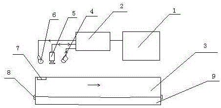
[0016] Such as figure 1 As shown, the present invention includes a PC terminal 1, which is also connected to an image acquisition card 2, and the image acquisition card 2 is connected to a workpiece detection locator 4, a CCD camera 5 and an LED light source 6 at the same time. 4. A main conveyor belt 3 is also arranged below the CCD camera 5 and the LED light source 6, a laser sensor 7 is also arranged at the entrance of the main conveyor belt 3, and an auxiliary conveyor belt 9 is also arranged on the side of the main conveyor belt 3. The main conveyor belt 3 and the auxiliary conveyor belt 9 Vigorously connect between by connector 8. Wherein the PC terminal can be realized by adopting existing commonly used terminals, which is not where the improvement lies.

[0017] This device uses a CCD camera to convert the detected target into an image signal, transmits it to a special image acquisition card, converts it into a digital signal according to the pixel distribution, brigh...

Embodiment 2

[0019] This embodiment is preferably as follows on the basis of Embodiment 1: the CCD camera 5 is located between the workpiece detection locator 4 and the LED light source 6, and the LED light source 6, the CCD camera 5 and the workpiece detection locator 4 are arranged sequentially from the entrance of the main conveyor belt 3 , and lie on a straight line. The LED light source is located at the entrance of the main conveyor belt, which can better illuminate the incoming objects, so that the CCD camera behind can take clear pictures of the objects and further improve the accuracy of automatic recognition.

[0020] The CCD camera 5 can rotate at any angle. According to the position of the object entering the conveyor belt, the positioning of the workpiece detection locator is used to adjust the shooting angle of the CCD camera to obtain the best shooting picture, so that the automatic recognition can be quickly realized in the later stage.

[0021] The workpiece detection loc...


PUM


Abstract

The invention discloses a machine vision inspection terminal for articles. The machine vision inspection terminal comprises a PC terminal, wherein an image collecting card is also connected to the PC terminal, and is also connected with a workpiece detection positioner, a CCD camera and an LED light source; a main conveyor belt is also arranged under the workpiece detection positioner, the CCD camera and the LED light source; a laser sensor is also arranged at an inlet of the main conveyor belt, an assistant conveyor belt is also arranged on the side surface of the main conveyor belt, and the main conveyor belt and the assistant conveyor belt are movably connected through connecting fittings. According to the machine vision inspection terminal disclosed by the invention, through the structure, the machine vision inspection terminal can be adjusted according to the width of each article, so that parts can move on the best path, and vision inspection can be performed. Therefore, requirements for improving the accuracy of automatically recognizing the articles of different sizes are met.

Description

technical field [0001] The invention relates to the field of machine vision, in particular to a machine vision item inspection terminal. Background technique [0002] In some dangerous working environments that are not suitable for manual work or where artificial vision is difficult to meet the requirements, machine vision is often used to replace artificial vision; at the same time, in the process of mass industrial production, the efficiency and accuracy of using artificial vision to check product quality is low. , the use of machine vision inspection methods can greatly improve production efficiency and production automation. Moreover, machine vision is easy to realize information integration, and it is the basic technology to realize computer integrated manufacturing. It is precisely because the machine vision system can quickly obtain a large amount of information, and is easy to automatically process, and is also easy to integrate with design information and processin...

Claims


Application Information

Patent Timeline
Patent Type & Authority Applications(China)
IPC IPC(8): G01N21/84
CPCG01N21/84G01N2021/8455
Inventor 张楠魏艾
Owner CHENGDU BEISEN WEIREN TECH CO LTD
Why Eureka
Try Eureka