Reeling rack

A winch and skein technology, which is applied in the field of winch, can solve the problems that the yarn cannot be twisted well, the spinning process is not fine enough, and the spinning speed cannot be automatically adjusted, and the elastic tensioning mechanism can be achieved. The effect of tightness, ensuring spinning quality and improving tightness

Inactive Publication Date: 2016-07-20
TIANJIN HAOSHI CARPET
View PDF1 Cites 3 Cited by
  • Summary
  • Abstract
  • Description
  • Claims
  • Application Information

AI Technical Summary

Problems solved by technology

At the same time, through the setting of the size scale, the diameter of each support rod can be more intuitive, but this kind of spinning process cannot perform yarn twisting well, the spinning process is not fine enough, and the spinning speed cannot be adjusted. self-adjusting drive

Method used


Image

  • Reeling rack

Examples


Embodiment 1

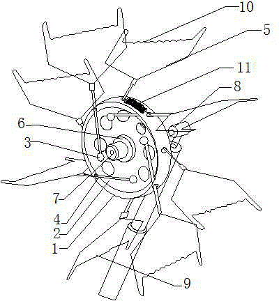
[0016] Such as picture A hank creel shown in 1 includes a sleeve 1; an isolation plate 2 is installed in the middle of the sleeve; studs 3 are respectively installed on the front side and the rear side of the isolation plate; A plurality of through-holes 4 are arranged at intervals on the sleeve wall; a skein arm 5 is installed on the inside of the through-hole 4; the inner side of the skein arm 5 is fixed on the stud 3; the middle part of the isolation plate 2 is installed with a bearing 6. A shaft 7 is installed inside the bearing 6; a rear bearing 8 is installed on the rear side of the shaft 7; a support shaft 9 is installed at the bottom of the rear bearing 8; four shafts are installed on the front and rear sides of the sleeve 1 respectively. The skein arms 5; elastic tensioning mechanisms 11 are installed between the adjacent skein arms 5.

Embodiment 2

[0018] Such as picture A hank creel shown in 1 includes a sleeve 1; an isolation plate 2 is installed in the middle of the sleeve; studs 3 are respectively installed on the front side and the rear side of the isolation plate; A plurality of through-holes 4 are arranged at intervals on the sleeve wall; a skein arm 5 is installed on the inside of the through-hole 4; the inner side of the skein arm 5 is fixed on the stud 3; the middle part of the isolation plate 2 is installed with a bearing 6; the inner side of the bearing 6 is equipped with a rotating shaft 7; the rear side of the rotating shaft 7 is equipped with a rear bearing 8; the bottom of the rear bearing 8 is installed with a support shaft 9; the rear side of the rear bearing 8 can also be installed with a power motor (not picture shown); the front side and the rear side of the sleeve 1 are respectively equipped with four skein arms 5; elastic tensioning mechanisms 11 are installed between the adjacent skein arms 5. ...


PUM


Abstract

The invention discloses a reeling rack which comprises a sleeve, wherein a separation plate is installed in the middle of the sleeve; studs are installed on the front side and the rear side of the separation plate respectively; multiple through holes are formed in a crossed manner at intervals on the sleeve walls located on the front and rear sides of the separation plate; reeling arms are installed on the inner side of the through holes; the inner sides of the reeling arms are fixed on the studs; a bearing is installed on the middle part of the separation plate; a spindle is installed on the inner side of the bearing; a rear bearing is installed on the rear side of the spindle; and a supporting shaft is installed on the bottom of the rear bearing. The reeling rack disclosed by the invention is characterized in that operations are simple; through crossed disposition of the front and rear through holes, multiple sets of reeling arms can be disposed, so that the shape of the reeling arms can further approach a round shape, tightness of yarn winding is increased, and spinning quality is ensured; automatic adjustment and driving can be carried out by a power motor according to spinning speeds; the height of a yarn installation place can be adjusted by a telescopic rod; and yarns can be supplied uniformly by yarn grasping grains, and an elastic tensioning mechanism can become more compact.

Description

technical field [0001] The invention relates to a yarn creel and belongs to the technical field of spinning machinery components. Background technique [0002] The textile machine twists many plant fibers together and spins them into threads or yarns, which can be used to weave cloth; The yarn production efficiency is not high; and the yarn synthesis spacing is not uniform enough, and the quality is not high enough; Chinese patent application number 201420257628.5 discloses a yarn creel, including a base body, which is an annular structure, connected to a rotating shaft, and the base body is an annular Hollow structure, at least four support rods are evenly spaced on the base body, the support rods extend into the hollow structure of the base body, and can be freely expanded and contracted on the base body, and the top of the support rods is provided with a supporting yarn horizontal plate. A connection plate is provided at the middle position of one side of the rod, a thro...

Claims


Application Information

Patent Timeline
Patent Type & Authority Applications(China)
IPC IPC(8): D02H13/00D02H9/00
Inventor 张淑芹赵昌盛
Owner TIANJIN HAOSHI CARPET
Why Eureka
Try Eureka