valve

A valve and spool technology, applied in the direction of valve lift, valve details, valve device, etc., can solve the problems of occupying the external space of the valve body, many parts of the transmission device, and shorten the life of the valve, so as to achieve small valve opening torque and space utilization High efficiency and excellent sealing effect

Active Publication Date: 2019-03-05
SHANGHAI HONGYAN RETURNABLE TRANSIT PACKAGINGS CO LTD
View PDF7 Cites 0 Cited by
  • Summary
  • Abstract
  • Description
  • Claims
  • Application Information

AI Technical Summary

Problems solved by technology

When the valve stem and the rotating disk rotate counterclockwise, under the forced action of the "brace" track on the rotating disk, the limit pin and the sealing structure of the valve first gather toward the center of the fixed disk according to the track of the "straight line" track on the fixed disk. , and then rotate counterclockwise according to the track of the "arc" track on the fixed plate, and the valve opens. The technical disadvantage of this patent is that it uses the track of "arc and straight line", which requires high precision and complicated processing technology. The valve core is a combination It is difficult to obtain a balanced pre-tightening force, resulting in damage to the valve core and shortening the life of the valve
[0005] A patent introduces an orbital plug valve, which includes a valve body, a valve cover, an operating part, a valve stem, a valve seat, a valve plug that forms a conical sealing pair with the valve seat, and an orbital mechanism. The orbital mechanism is installed on the The valve plug neck is composed of an orbital ring with two guide grooves and a double-pin plate with two guide pins pinned into the guide grooves, and also includes a lock nut and an adjustment ring for adjusting the installation position of the orbital ring. The disadvantage of this patent is The structure of the transmission device is complex, which greatly occupies the external space of the valve body; the transmission device involves many parts and the assembly process is complicated; in addition, due to the valve plug of the conical sealing pair, as well as the lock nut and the adjustment ring for adjusting the installation position of the orbital ring, It requires multiple adjustments, so the operation is complicated

Method used


Image

  • valve
  • valve
  • valve

Examples


Embodiment Construction

[0049] Preferred embodiments of the present invention will be described in detail below in conjunction with the accompanying drawings, so as to better understand the purpose, features and advantages of the present invention. It should be understood that the embodiments shown in the drawings are not intended to limit the scope of the present invention, but only to illustrate the essence of the technical solution of the present invention.

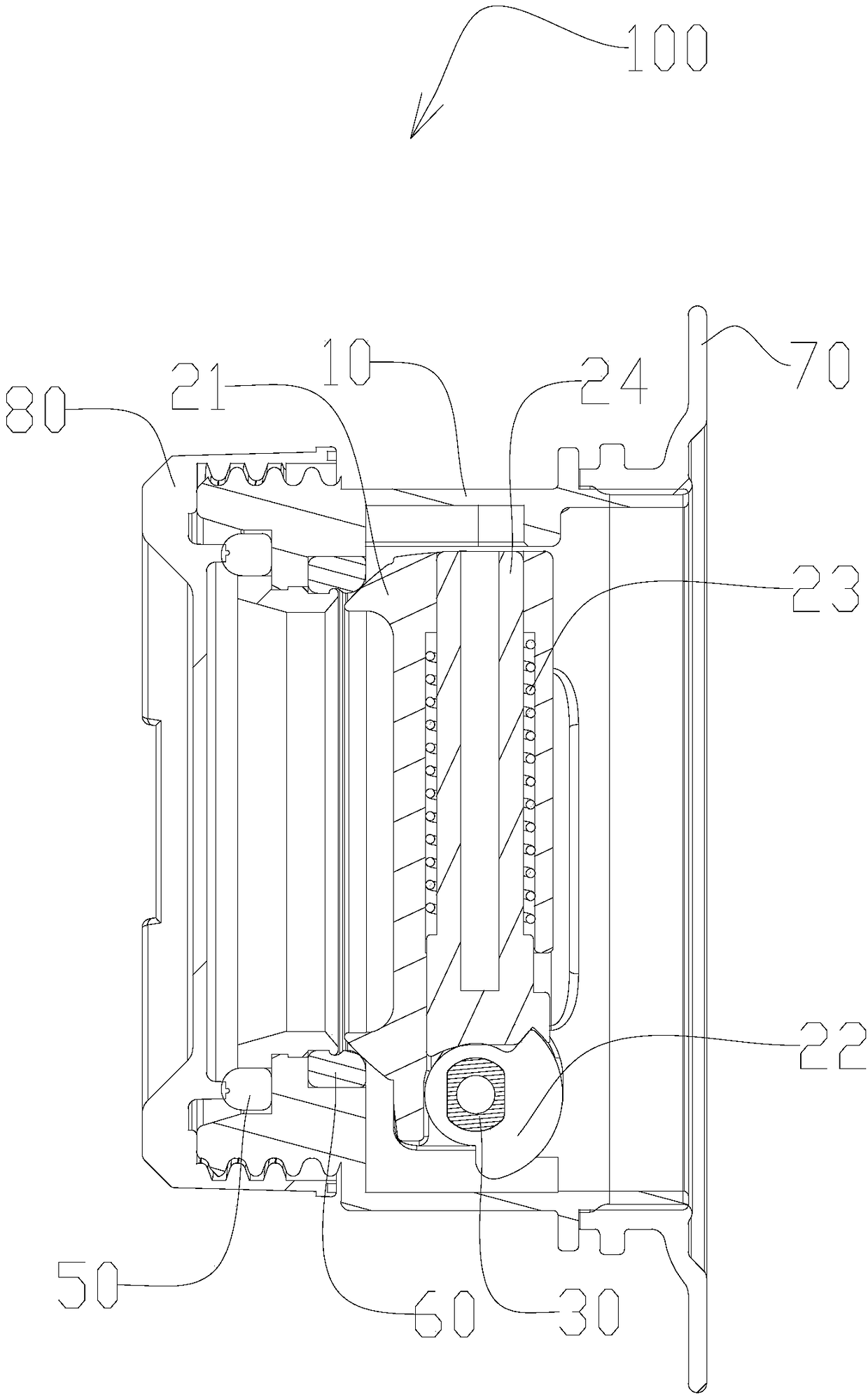
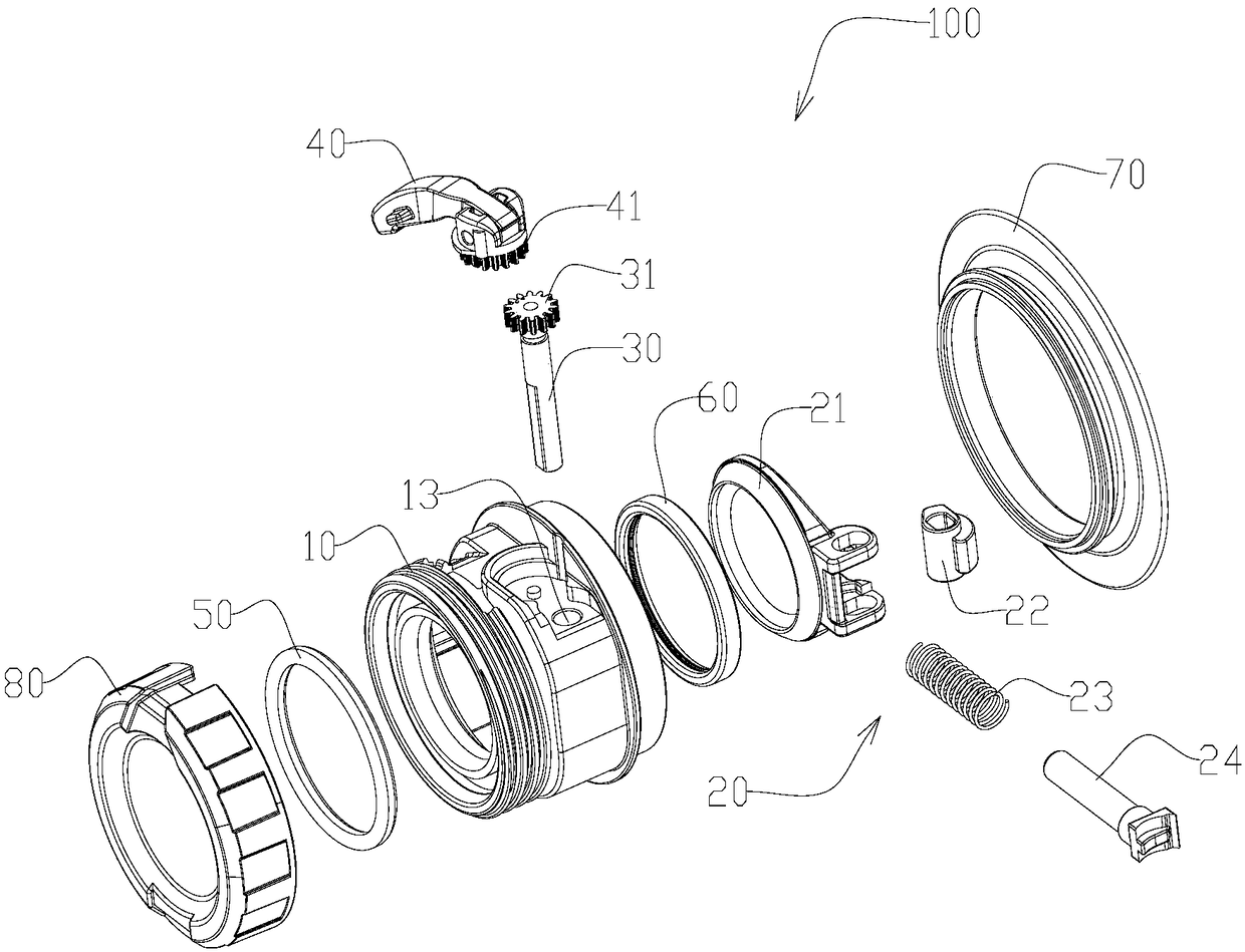
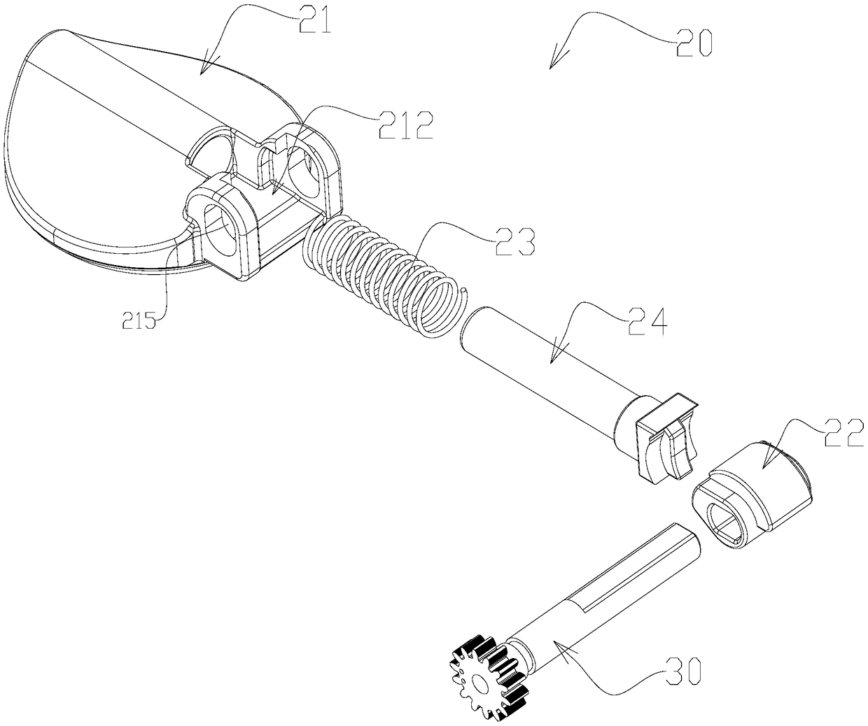
[0050] According to one aspect of the present invention, the valve generally includes a valve body, a valve stem, a valve seat and a valve core assembly, the valve core assembly is installed in the valve body and includes a valve core, and the valve core is hinged to the valve body. The spool assembly further includes a driving part, a positioning part and an elastic part, wherein the positioning part is mounted on the valve core in a relatively movable manner, the elastic part is installed between the positioning part and the valve core, and ...


PUM


Abstract

The invention discloses a valve, which comprises a valve body, a valve stem, a valve seat and a valve core assembly. The valve core assembly is installed in the valve body and includes a valve core, the valve core is hinged to the valve body, and the valve core assembly further includes a driving part, a positioning part and an elastic part. Among them, the positioning part can be installed on the valve core in a relatively movable manner, the elastic part is installed between the positioning part and the valve core, and the coupling relationship between the driving part and the positioning part can make the valve have three transmission relationships during the closing process: the driving part Cooperate with the positioning part to form a relatively static first transmission relationship; the driving part squeezes the positioning part to make the positioning part perform a second transmission relationship relative to the valve core; the driving part and the positioning part are switched from the second transmission relationship to driving The third transmission relationship between the component and the spool. The valve of the invention has the beneficial effects of few parts, good manufacturing process, simple structure and high space utilization rate.

Description

technical field [0001] The invention relates to a storage container, in particular to a valve. Background technique [0002] Existing valves for medium-sized bulk storage containers, such as butterfly valves, are opened by selecting the middle shaft of the valve core, which drives the valve core to rotate on both sides to open, because the valve core is generally located inside the valve body, and its flow is affected by the valve core and the shaft ; Poor sealing. Due to the friction between the sealing ring of the butterfly valve and the valve body, the force to open and close the valve is relatively large. [0003] Recently, a guide groove type lifting rod ball valve has been developed at home and abroad. There is an S-shaped guide groove on the valve stem, which cooperates with the guide pin, so that when the valve stem rises, it drives the ball away from the valve seat, and then rotates 90° counterclockwise to fully open the valve. When the valve stem is lowered, it d...

Claims


Application Information

Patent Timeline
Patent Type & Authority Patents(China)
IPC IPC(8): F16K1/18F16K1/36F16K31/524
CPCF16K1/18F16K1/36F16K31/52441F16K1/2014F16K31/535F16K31/602F16K27/0227F16K1/2007F16K1/24
Inventor 不公告发明人
Owner SHANGHAI HONGYAN RETURNABLE TRANSIT PACKAGINGS CO LTD
Why Eureka
Try Eureka