Distributed passive radar target detection method under direct wave-free condition

A technology of target detection and passive radar, which is applied in radio wave measurement system, radio wave reflection/reradiation, measurement device, etc. It can solve the problem of undetectable target, impossible to completely eliminate mismatch, mismatch of transmitted signal, etc. problem, to achieve the effect of avoiding target matching problem and ambiguous positioning problem

Active Publication Date: 2016-08-24
NAVAL AVIATION UNIV
View PDF4 Cites 16 Cited by
  • Summary
  • Abstract
  • Description
  • Claims
  • Application Information

AI Technical Summary

Problems solved by technology

[0005] However, in distributed passive radar, if the signal-to-noise ratio of the direct wave signal is relatively low, the transmitted signal cannot be estimated with high quality, which will cause a mismatch with the real transmitted signal, the detection performance will decrease, and even the target cannot be detected
Although the effect of mismatch can be mitigated to some extent by channel equalization, it is impossible to completely eliminate the mismatch
In addition, due to the influence of complex terrain environment in practice, if there is physical occlusion in the line-of-sight propagation path between the non-cooperative radiation source and the receiver, the passive radar will not be able to receive the direct wave signal from the non-cooperative radiation source. The target detection cannot be completed by using the classical matched filter theory
Therefore, the target detection method by calculating the cross-ambiguity function or generalized cross-correlation between the received signals of the reference channel and the monitoring channel is not suitable for the situation where the direct wave signal-to-noise ratio is very low or the direct wave signal is not received at all.

Method used


Image

  • Distributed passive radar target detection method under direct wave-free condition
  • Distributed passive radar target detection method under direct wave-free condition
  • Distributed passive radar target detection method under direct wave-free condition

Examples


Embodiment Construction

[0026] The present invention will be described in further detail below in conjunction with the accompanying drawings.

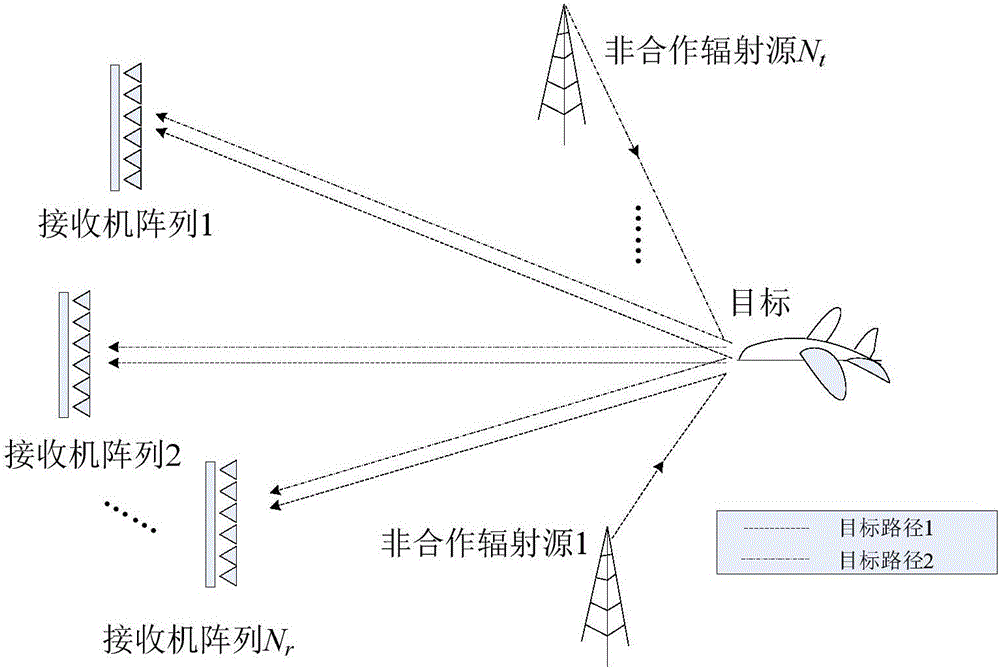
[0027] like figure 1 As shown, the distributed passive radar system includes N t transmitters, which are also called non-cooperative radiation sources in the field of passive radar, N r receiver array, 1 target, where N t ≥2,N r ≥2.

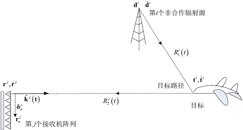
[0028] like figure 2 As shown, the geometric relationship and signal environment of the ij-th bistatic pair, the position and velocity of the i-th transmitter are denoted as d i and i=1,...,N t , the position and velocity of the jth receiver array are denoted as r j and j=1,...,N r , while the position and velocity of the target are denoted as t and where d i , r j , t, are all functions of time. In general, the transmitter and receiver, and the target are moving. The distance from the i-th transmitter to the j-th receiver is Similarly, and represent the distance from the i-th transmitter to the ta...


PUM


Abstract

The invention discloses a distributed passive radar target detection method under a direct wave-free condition, and belongs to the technical field of distributed passive radar target detection. A conventional passive radar target detection method is based on the classical matched filtering theory, and approximately optimal detection properties can be achieved on premise that a direct wave with a relatively high signal-to-noise ratio can be acquired in real time and an emitted signal can be estimated with high quality by using a direct wave signal received by a reference channel. To solve the problem of detecting a target which cannot receive the direct wave signal in practical, the invention discloses the distributed passive radar target detection method under a direct wave-free condition, and a concentrated target detector under the direct wave-free condition is established, so that target detection can be implemented when the signal-to-noise ratio of the direct wave signal is relatively low or the direct wave signal cannot be received in a multiple-input multiple-output geometric structure, and meanwhile the target matching problem which is very hard to solve among different receiving stations of a distributed passive radar is indirectly avoided.

Description

technical field [0001] The invention belongs to the technical field of distributed passive radar target detection, in particular to a method for distributed passive radar target detection under the condition of no direct wave. Background technique [0002] Many experiments at home and abroad have proved that the passive radar based on the third-party non-cooperative radiation source has good detection potential, and can realize the detection and positioning of small air targets and low-altitude flying targets. In order to further improve target detection stability and tracking continuity, many research institutions in Europe and the United States have carried out research on distributed passive radar technology based on multiple transmission and multiple reception systems of FM, DAB, DVB-T, and GPS signals. [0003] At present, the target detection method of distributed passive radar is based on the classic matched filter theory, that is, using each transmitter-target-receiv...

Claims


Application Information

Patent Timeline
Patent Type & Authority Applications(China)
IPC IPC(8): G01S13/56
CPCG01S13/56
Inventor 张财生唐小明朱洪伟刘明春李国君张涛宋洪良
Owner NAVAL AVIATION UNIV
Why Eureka
Try Eureka