Sheet metal bending machine

A technology for bending machines and metal plates, applied in the field of bending machines, can solve the problems of reducing machine output, expensive automatic systems, and high operation cycle duration, and achieves the effect of increasing cycle duration.

Active Publication Date: 2018-10-30
SALVAGNINI ITAL
View PDF15 Cites 0 Cited by
  • Summary
  • Abstract
  • Description
  • Claims
  • Application Information

AI Technical Summary

Problems solved by technology

[0010] A disadvantage of known bending machine tools is that in order to perform bends with different lengths, it is necessary to change the tool in order to perform a tool combination with the desired length
In order to perform assembly and / or disassembly operations of tools which must be withdrawn and / or placed in magazines, considerable time intervals are necessary during which the machine must be stopped, interrupting production and thereby reducing machine output
[0011] Furthermore, tool changes and / or positioning can only be performed at the beginning of a workpiece operation cycle, not during said cycle
In fact, in this case, the duration of the operating cycle will be too high, reducing the output of the machine
Another disadvantage of the known bending machines is that automatic systems for tool change and assembly are expensive and complex, since gripping and transfer devices are required to assemble and disassemble the bending tools and to withdraw and insert the bending tools into the suitable box

Method used


Image

  • Sheet metal bending machine
  • Sheet metal bending machine
  • Sheet metal bending machine

Examples


Embodiment Construction

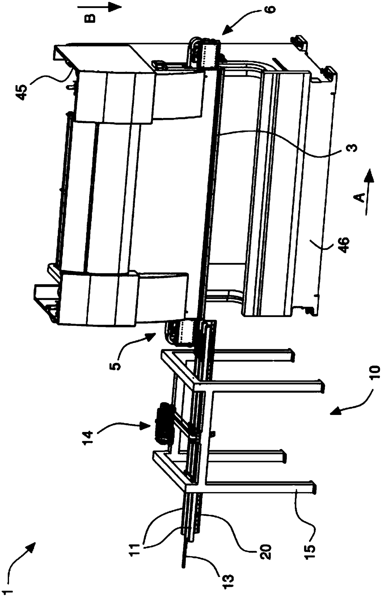
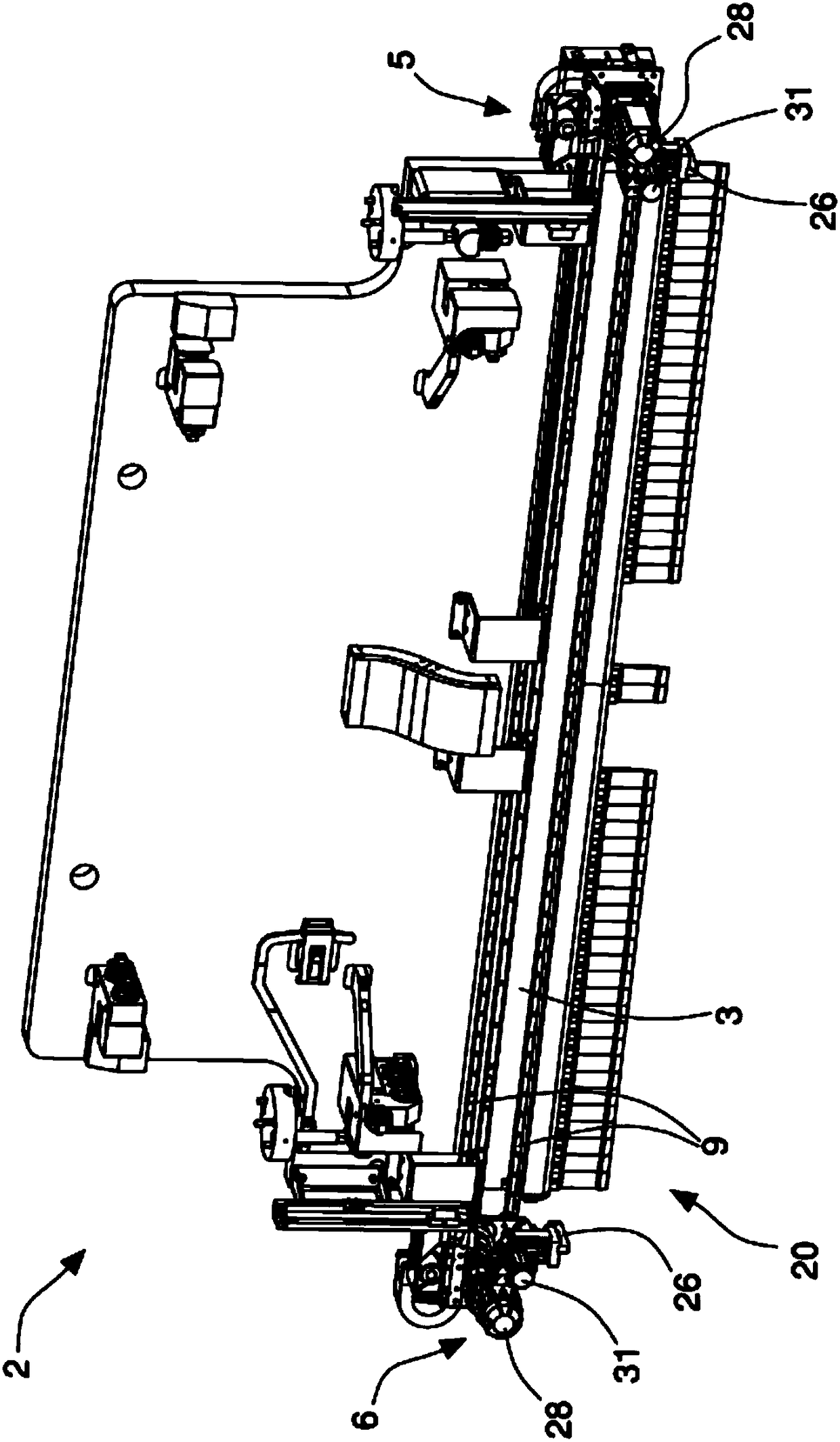
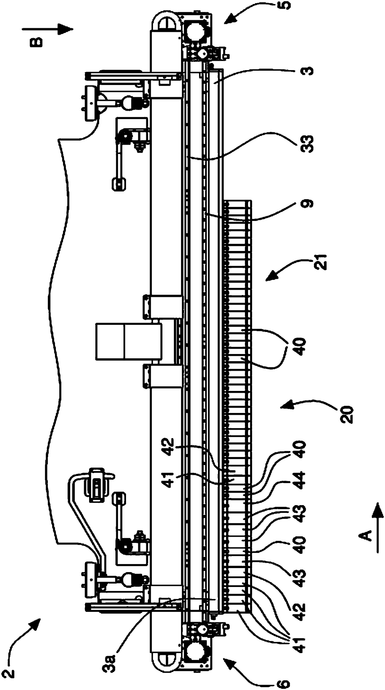
[0060] refer to Figure 1 to Figure 12 , shows a sheet metal bending machine 1 according to the invention comprising a bending assembly 2 provided with a tool holder beam 3 which is movable and supports a set of 20 bending tools 40, 41, 42, 43, 44, so-called bending blades or segments, the set of bending tools arranged adjacently aligned along a first longitudinal direction A and mutually positionable so as to form The predetermined tool combinations C1 , C2 , C3 , C4 of the workpiece 50 are bent using the defined bend lines. The first direction A is parallel to the bending line on which the bending takes place on the workpiece 50 . The set of 20 bending tools forms a modular and mated punch that is slidable and adjustable along the tool holder beam 3 of the bending machine.

[0061] The bending assembly 2 comprises movement means 5 , 6 for the appropriate movement and positioning of the bending tools 40 , 41 , 42 , 43 , 44 along the beam 3 . The mobile devices 5 , 6 are co...


PUM


Abstract

A bending machine for sheet metal, comprising a bending assembly (2) provided with a tool holder beam (3) which is a movable and supports a set (20) of bending tools (40, 41, 42, 43, 44) that can be aligned and positioned relative to each other along a first longitudinal direction (A) to form a A predetermined combination (C1, C2, C3, C4) of bending tools for bending the workpiece (50) according to the defined bending line; the bending assembly (2) includes a moving device (5, 6), and the moving device makes Bending tools (40, 41, 42, 43, 44) move along the beam (3), said set (20) of bending tools comprising adjacent one end (3a) of said beam (3) ground and arranged in sequence: four first bending tools (41) having a width equal to X+p; one second bending tool (42) having a width equal to X+2-p; having a width equal to X One third bending tool (43) of +3‑p; one basic bending tool (40) with width equal to X; three third bending tools (43); one with width equal to X+4‑p A fourth bending tool (44); two basic bending tools (40); a first bending tool (41); a second bending tool (42); another set of (21) basic bending tools ( 40); where X is the basic width of said basic bending tool (40) in millimeters comprised between 30 and 70 mm; and p is the a step between two lengths comprised between 5 and 20 mm; the combination of one or more adjacent tools (40, 41, 42, 43, 44) of said set (20) of bending tools allows to Said steps (p) obtain bends of all lengths starting from the smallest bend length equal to said basic width (X).

Description

technical field [0001] The invention relates to a bending machine arranged to bend and deform strips, sheet metal, metal section bars in order to obtain semi-finished and / or finished products. In particular, the present invention relates to a bending machine having modular and mating punches consisting of a tool holder crosspiece slidably and adjustably secured to the machine. Group bending tools form. The invention also relates to a bending machine provided with a system for automatically changing and / or positioning said bending tools. Background technique [0002] Bending machines are known, also called press brakes, which comprise a mechanically or hydraulically driven press capable of moving an upper tool, called a punch, against a lower tool, called a die, positioning the workpiece on the lower tool. The punch exerts a force on the workpiece that can deform and bend the workpiece according to angles determined by the configuration of the tool itself. [0003] One ty...

Claims


Application Information

Patent Timeline
Patent Type & Authority Patents(China)
IPC IPC(8): B21D5/02B21D37/14
CPCB21D5/0218B21D37/145B21D5/02B21D5/004B21D5/0254B21J13/08B21D37/14
Inventor N·梅内盖蒂
Owner SALVAGNINI ITAL
Why Eureka
Try Eureka