Large-thrust high-speed hydraulic cylinder and work method thereof

A hydraulic cylinder and high-thrust technology, applied in the hydraulic field, can solve problems such as difficulty in providing high output speed, achieve the effects of shortening work preparation time, compact system structure, and improving energy utilization

Active Publication Date: 2016-10-12
TIANJIN URANUS HYDRAULIC MACHINERY
View PDF8 Cites 2 Cited by
  • Summary
  • Abstract
  • Description
  • Claims
  • Application Information

AI Technical Summary

Problems solved by technology

The hydraulic system has the advantages of large thrust and compact structure, and is an ideal test acceleration system. However, the existing traditional hydraulic cylinder is used as a power source, and the movement speed of its piston rod is limited by many aspects such as liquid flow, so it is difficult to provide high output speed

Method used


Image

  • Large-thrust high-speed hydraulic cylinder and work method thereof
  • Large-thrust high-speed hydraulic cylinder and work method thereof
  • Large-thrust high-speed hydraulic cylinder and work method thereof

Examples


Embodiment Construction

[0036] The present invention will be described in further detail below with reference to the drawings and specific embodiments. The following embodiments are only descriptive and not restrictive, and the protection scope of the present invention cannot be limited by this.

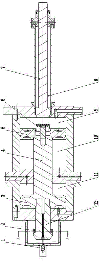
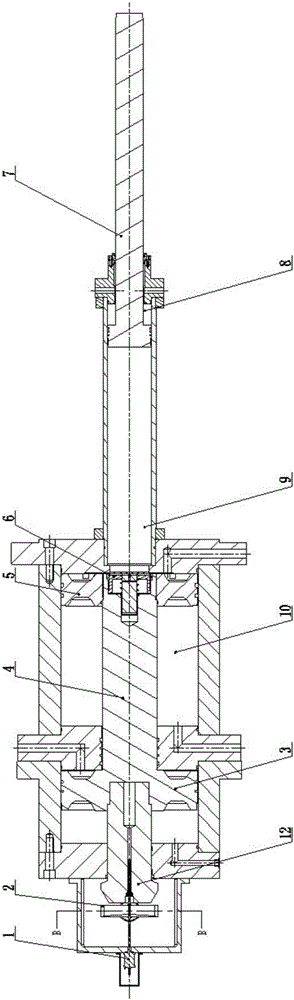
[0037] A high-thrust, high-speed hydraulic cylinder includes a high-speed hydraulic cylinder, a piston-type accumulator, and a pressure-increasing sensor. One axial end of the hydraulic cylinder is equipped with a high-speed cylinder piston rod, and the other axial end of the hydraulic cylinder is connected in series with a piston-type accumulator. Piston-type accumulator increases the speed of pushing out the piston rod;

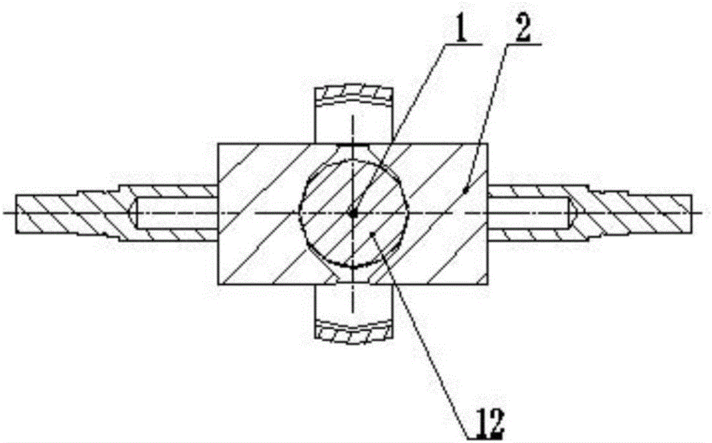
[0038] In order to facilitate the description of this embodiment, attach figure 1 The directions shown are for explanation, the left side is the back and the right side is the front. The specific structure is:

[0039] The main body of the hydraulic cylinder is a horizontally arranged sealed ca...


PUM


Abstract

The invention relates to a large-thrust high-speed hydraulic cylinder. A hydraulic cylinder body is a sealed cavity which is transversely arranged. A high-speed cylinder barrel is fixedly arranged at the front end of the hydraulic cylinder body in an axial extending manner. A high-speed cylinder piston rod is coaxially sleeved with the high-speed cylinder barrel. The high-speed piston rod coaxially slides in a sealed manner in a high-speed cylinder rod cavity. An energy accumulator piston rod penetrating an energy accumulator gas cavity and a supercharger cavity is coaxially installed in the hydraulic cylinder body. An energy accumulator piston is fixedly arranged at the end portion, at the front end of the energy accumulator gas cavity, of the energy accumulator piston rod. The energy accumulator piston is installed in the hydraulic cylinder body in a sealed and sliding manner. An energy accumulator liquid cavity is formed between the energy accumulator piston and the high-speed cylinder piston rod. A pressure cylinder piston is coaxially manufactured on the energy accumulator piston rod in the supercharger cavity. The pressure cylinder piston is installed in the supercharger cavity in a sealed and sliding manner. By means of the high-thrust high-speed hydraulic cylinder, through the manner that a piton type energy accumulator and the high-speed hydraulic cylinder are directly connected in series, high-speed output of large thrust of the high-speed cylinder can be achieved.

Description

Technical field [0001] The invention belongs to the field of hydraulics, in particular to a large-thrust, high-speed hydraulic cylinder and a working method thereof. Background technique [0002] In various engineering applications such as crash tests, high-speed friction tests, or high-speed launching devices, it is usually necessary to accelerate large-mass test platforms or test objects to reach higher working speeds quickly. This puts forward the acceleration system of the test bench Very high job requirements. The hydraulic system has the advantages of large thrust and compact structure. It is an ideal test acceleration system. However, the existing traditional hydraulic cylinder is used as a power source, and its piston rod movement speed is restricted by many aspects such as liquid flow, so it is difficult to provide high Output speed. Summary of the invention [0003] The purpose of the present invention is to overcome the shortcomings of the prior art, and provide a hig...

Claims


Application Information

Patent Timeline
Patent Type & Authority Applications(China)
IPC IPC(8): F15B3/00F15B15/17F15B1/02F15B15/28
CPCF15B1/02F15B3/00F15B15/17F15B15/2815F15B2201/20F15B2201/31
Inventor 李晓龙王超光刘兵于安才张建
Owner TIANJIN URANUS HYDRAULIC MACHINERY
Why Eureka
Try Eureka