Bamboo-tube slicing device

A technology of bamboo tubes and blades, which is applied in the direction of wood splitting devices, wood processing equipment, manufacturing tools, etc., can solve the problems of bamboo tubes and knives being easily damaged, uneven width of bamboo prongs, and large labor workload of workers, so as to achieve uniform width and wide adaptability Sexuality and high efficiency

Active Publication Date: 2016-11-09
郯城县精华种业有限公司
View PDF8 Cites 7 Cited by
  • Summary
  • Abstract
  • Description
  • Claims
  • Application Information

AI Technical Summary

Problems solved by technology

Therefore, a large number of bamboo prongs will be used in the process of planting crops. The traditional method is to split the bamboo tube manually with a knife. On the one hand, the efficiency is low, and the labor load of the workers is large. On the other hand, the width of the bamboo prongs obtained is not uniform. , the third is that bamboo prongs are easy to split, and bamboo tubes and knives are easily damaged

Method used


Image

  • Bamboo-tube slicing device
  • Bamboo-tube slicing device
  • Bamboo-tube slicing device

Examples


Embodiment 1

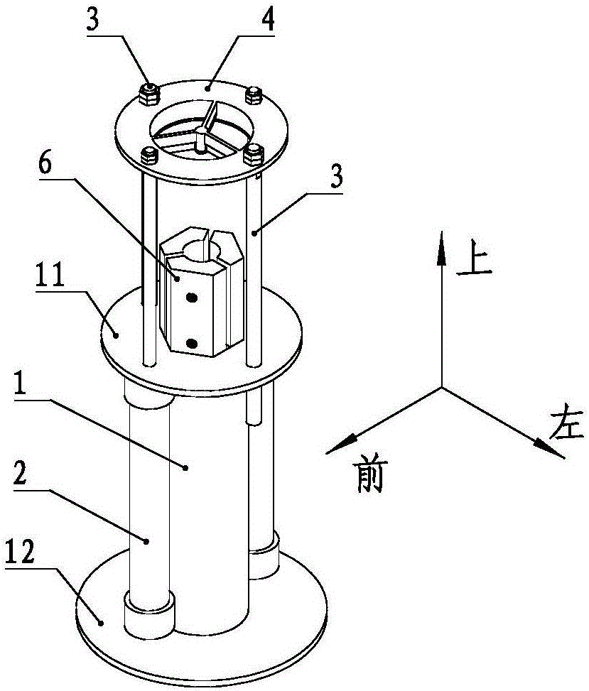
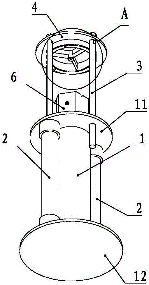
[0032] For the convenience of description, the coordinate system is defined as figure 1 shown.

[0033] Such as figure 1 and figure 2 As shown, a bamboo tube slicing device includes a cylindrical base 1, a knife rest 4, a blade 5 and a positioning mechanism 6, and the upper and lower ends of the base 1 are respectively provided with an upper circular plate 11 and a lower circular plate 12. . Between the upper circular plate 11 and the lower circular plate 12, a cylinder 2 is respectively arranged on the front and rear sides of the base 1, the cylinder body of the cylinder 2 is fixedly connected with the upper circular plate 11, and the cylinder 2 is fixedly connected with the said knife rest 4 after passing through the upper circular plate 11. The left and right sides of the base 1 are respectively provided with guide posts 3 between the knife rest 4 and the base 1, the upper ends of the guide posts 3 are fixedly connected with the knife rest 4, and the guide posts The l...

Embodiment 2

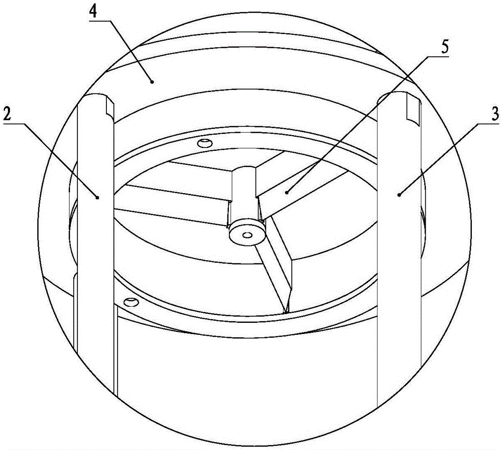
[0038] Between the outer ring 41 and the central cylinder 42, four ribs 43 are arranged radially and evenly, and each of the ribs 43 is provided with a first groove 431 along the axial direction. Blade 5 is arranged inside. The corresponding positioning structure includes a positioning block 61 with a regular octagonal cross section, and the third groove is a regular octagonal shape. The side of the positioning block 61 is provided with four second grooves 62 along the axial direction and communicating with each other, and the four second grooves 62 correspond to the four ribs 43 one by one. All the other structures are the same as in Embodiment 1.


PUM


Abstract

The invention discloses a bamboo-tube slicing device. The bamboo-tube slicing device comprises a base, a knife rest, a blade and a positioning mechanism, wherein the upper end and the lower end of the base are respectively provided with an upper round plate and a lower round plate; cylinders are arranged at the positions between the upper round plate and the lower round plate and at the front side and the rear side of the base; cylinder bodies of the cylinders are fixedly connected with the upper round plate; piston rods of the cylinders penetrate through the upper round plate and are fixedly connected with the knife rest; guiding columns are arranged at the positions between the knife rest and the base and at the left side and the right side of the base. A positioning mechanism and a positioning-mechanism positioning block are arranged on the base and between the knife rest and the base; the positioning block is provided with a bamboo-tube installing hole along the axial direction; the side surface of the positioning block is provided with a plurality of second grooves which are communicated along the axial direction, and the second grooves correspond to rib plates in a manner of one-to-one correspondence. An elastic positioning component is arranged between the adjacent second grooves. The bamboo-tube slicing device disclosed by the invention has the advantages that not only is the processing efficiency high, but also the width of obtained bamboo sticks is uniform.

Description

technical field [0001] The invention relates to the technical field of crop planting, in particular to a bamboo tube slicing device for processing bamboo chips for crop planting. Background technique [0002] In the process of crop planting, in order to assist the overall layout of planting (crop plot test, rice transplanting, etc.), so that the row spacing of crop planting is even and tidy, a large number of field test ropes will be used. When the test rope is set, generally two bamboo prongs are utilized to fix the end of the line and the end of the line of the test rope to the two ends of the field according to the required direction. Therefore, a large number of bamboo prongs will be used in the process of planting crops. The traditional method is to split the bamboo tube manually with a knife. On the one hand, the efficiency is low, and the labor load of the workers is large. On the other hand, the width of the bamboo prongs obtained is not uniform. The third is that t...

Claims


Application Information

Patent Timeline
Patent Type & Authority Applications(China)
IPC IPC(8): B27L7/06
CPCB27L7/06
Inventor 陈峰姜明松崔太昌朱文银徐建第周学标李景岭李广贤袁守江张洪瑞王瑜
Owner 郯城县精华种业有限公司
Why Eureka
Try Eureka