Micro heat pipe and manufacturing method of micro heat pipe

A technology of micro heat pipes and manufacturing methods, which can be applied to indirect heat exchangers, lighting and heating equipment, etc., and can solve problems such as post-processing difficulties

Inactive Publication Date: 2017-01-11
ACMECOOLS TECH
View PDF12 Cites 3 Cited by
  • Summary
  • Abstract
  • Description
  • Claims
  • Application Information

AI Technical Summary

Problems solved by technology

Whether it is setting grooves in the tube, laying copper powder or copper mesh, and even post-processing are very difficult, there is currently no known technology that can effectively solve this problem

Method used


Image

  • Micro heat pipe and manufacturing method of micro heat pipe
  • Micro heat pipe and manufacturing method of micro heat pipe
  • Micro heat pipe and manufacturing method of micro heat pipe

Examples


no. 1 example

[0054] By performing the above steps, a micro heat pipe 10 can be manufactured. The use of the micro heat pipe 10 and the achievable effects have been described in the first embodiment, and will not be repeated here.

[0055] Such as Figure 17 As shown, the second embodiment may further include a marking step: a mark 19 is provided on the surface of the tube 11 so that the position of the heated section H can be identified. Thereby, the user can judge the position of the heated section H of the micro heat pipe 10 from the appearance of the micro heat pipe 10. The setting method of the mark 19 has been described in the first embodiment, and will not be repeated here.

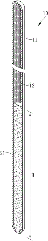
[0056] In the second embodiment, in the foregoing preparation step, the prepared tube 11 may also be a grooved tube, that is, the inner tube wall of the tube 11 is provided with a plurality of grooves extending in the axial direction. The grooves 14, thereby, in the foregoing etching step, the first capillary struc...


PUM


Abstract

The invention discloses a micro heat pipe. The micro heat pipe comprises a pipe body, a second capillary structure and acting liquid, wherein the two ends of the pipe body are closed, a heated section, a heat insulation section and a condensation section are defined from one end to the other end of the pipe body along the body part of the pipe body; an etching line which is formed after etching is arranged on the inner wall of the pipe body, and the etching line is defined as a first capillary structure and distributed all over the heated section, the heat insulation section and the condensation section; the second capillary structure is arranged in the pipe body and located on the heated section of the pipe body, and the heated section is filled with the second capillary structure which has a liquid adsorbing capillary effect; and the acting liquid is injected into the pipe body. The invention further discloses a manufacturing method of the micro heat pipe. The manufacturing method of the micro heat pipe mainly comprises the steps that the inner wall surface of the pipe body is etched for forming the first capillary structure, liquid injection, vacuumizing and sealing are conducted after the heated section is filled with the second capillary structure and sintered, and then the micro heat pipe is obtained.

Description

Technical field [0001] The present invention relates to a heat sink, and particularly refers to a micro heat pipe and a method for manufacturing the micro heat pipe. Background technique [0002] The heat pipe is a kind of capillary material formed by copper powder or metal mesh inside, and after injecting an appropriate amount of working fluid, the two ends are closed. Patent No. TW I447342 of Taiwan, China discloses a heat pipe with a composite capillary structure, which has a second internal tube body with copper powder and grooves to form a composite capillary structure. In addition, Taiwan Patent No. TW M499544 discloses a heat pipe with multiple capillary structures. [0003] However, whether it is the heat pipes of the aforementioned two patents or the currently known heat pipes, the main specifications are 6 millimeters (mm) in diameter. At present, there is no stable and effective technology that can produce a diameter of 3 mm ( mm) and the heat pipes with a diameter of ...

Claims


Application Information

Patent Timeline
Patent Type & Authority Applications(China)
IPC IPC(8): F28D15/04
Inventor 金积德
Owner ACMECOOLS TECH
Why Eureka
Try Eureka